
User's Guide


Program Operation 15
Affinity Control User’s Guide
Software v2.50
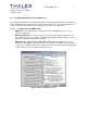
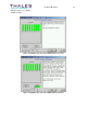
amplifier OFF is displayed below the amp. Note that the program does NOT actually know
which amplifier is being turned OFF and assumes that the operator is following the sequence as
highlighted. If the sequence is not followed correctly, the values under each amplifier block will
not be correct for the specific location shown.
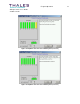
After all of the amplifiers have been tested, the program will calculate an average power drop
and highlight the amplifiers that have a gain contribution below a calculated limit.
NOTE: An amplifier making little or no contribution to the final output power (i.e. power drops little when
amp in question is deactivated) is most likely defective and may require replacement.
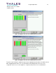
It is important to understand that the program only offers "advice." The operator should make
the final decision regarding which amplifier(s) is/are defective. It is strongly recommended that
the power levels shown for each amplifier be reviewed closely, that suspect amps be swapped
to a new location, and that the test be re-run before deciding that an amplifier has failed.
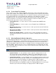
2.3 Full Upconverter Calibration Procedure
The Full Upconverter Calibration Procedure allows a new upconverter to be calibrated to the
system in which it operates. An average power meter and a selection of SMA or N attenuator
values are REQUIRED (a 0-10dB variable attenuator is recommended) in order to perform this
procedure. The program provides a step-by-step procedure with instructions for the entire
calibration. Each step is documented in this manual. This program performs some of the steps
listed below automatically. The steps that are performed are as follows:
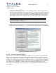
• Initialize the upconverter with default parameters.
• Put upconverter into ALC Manual mode.
• Check/adjust the ADAPT output level and connect to the RF input port of the
upconverter.
• Adjust the ALC Manual Ref value to bring the system to full power.
• Check/adjust and connect a forward power sample to the forward power sample input of
the upconverter.
• Adjust the System Fwd Pwr Ref value to calibrate the “System Fwd Pwr” metering value
displayed on the upconverter LCD.
• Adjust the Upconv Fwd Power Ref value to calibrate the “Upconv Fwd Pwr” metering
value displayed on the upconverter LCD.
• Check/adjust and connect a reflected power sample to the reflected power sample input
of the upconverter.
• Adjust the System Refl Power Ref value to calibrate the “System Refl Pwr” metering
value displayed on the upconverter LCD.
• Place upconverter into ALC Auto mode.
• Adjust the ALC Auto Ref value to bring the system to full power in ALC Auto mode.
• Calibrate the Power Limiter threshold to limit maximum system output power.