
Installation Manual

MALE FEMALE
Thomas & Betts Corp.
TIE 1
TIE 2
MDBOOT-0
MDBOOT-1
MDBOOT-2
MDBOOT-3
MDBOOT-4
WARNING
NOT FOR DISCONNECTING ENERGIZED CIRCUITS.
WARNING
RISK OF SHOCK, DISCONNECT
POWER BEFORE INSTALLATION.
#16-14
#16-14
#12-10
#8
#6
#12-10
#8
#6
#4
#2
#1
#6
#2
#1
#1/0
#2/0
#3/0
#4/0
#4/0
#250 kcmil
#350 kcmil
#500 kcmil
MD1614F-0
MD1614F-1
MD1210F-1
MD8F-1
MD6F-1
MD1210F-2
MD8F-2
MD6F-2
MD4F-2
MD2F-2
MD1F-2
MD6F-3
MD2F-3
MD1F-3
MD10F-3
MD20F-3
MD30F-3
MD40F-3
MD40F-4
MD250F-4
MD350F-4
MD500F-4
FEMALE
WIRE SIZE
AWG
MD1614M-0
MD1614M-1
MD1210M-1
MD8M-1
MD6M-1
MD1210M-2
MD8M-2
MD6M-2
MD4M-2
MD2M-2
MD1M-2
MD6M-3
MD2M-3
MD1M-3
MD10M-3
MD20M-3
MD30M-3
MD40M-3
MD40M-4
MD250M-4
MD350M-4
MD500M-4
MALE
MDBOOT-0
TY24M (2)
MDBOOT-1
TY24M (2)
MDBOOT-2
TY24M (2)
MDBOOT-3
TY242M (2)
MDBOOT-4
TYHT28M (2)
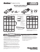
CATALOG NUMBERS
BOOT NO.
&
CABLE TIE
Sealant available, Catalog Number
MDBOOT-SEAL
TABLE I
Reference
Size
Group
TABLE II
#16-14
#12-10
#8
#6
#12-10
#8
#6
#4
#2
#1
#2
#1
#1/0
#2/0
#3/0
#4/0
M2D1614M-0
M2D1210M-1
M2D8M-1
M2D6M-1
M2D1210M-2
M2D8M-2
M2D6M-2
M2D4M-2
M2D2M-2
M2D1M-2
M2D2M-3
M2D1M-3
M2D10M-3
M2D20M-3
M2D30M-3
M2D40M-3
MDBOOT-1
M2DBOOT-1
TY242M (2)
M2DBOOT-2
TY242M (2)
M2DBOOT-3
TY26M
DOUBLE
MALE
MD1614F-0
MD1210F-1
MD8F-1
MD6F-1
MD1210F-2
MD8F-2
MD6F-2
MD4F-2
MD2F-2
MD1F-2
MD2F-3
MD1F-3
MD10F-3
MD20F-3
MD30F-3
MD40F-3
FEMALE
WIRE SIZE
AWG
CATALOG NUMBERS
BOOT NO.
&
CABLE TIE
NOTE: Some catalog numbers shown
above have sufxes: i.e. XXXXXG
(indicating special packaging). All crimp
settings for these parts are the same as
for the base numbers.
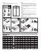
—INSTALLATION HINTS—
A. Always install the female lug on line leads and the male lug on the
motor leads for 600V and less, female on both line leads and motor
leads for the 5KV connection.
B. Always use the smallest body size for the lug possible for the
largest wire in the junction box. Line leads are usually the largest.
C. Store the boots and bolts from the junction box in the re-closeable
plastic bag provided. Use a Ty-Rap
®
cable tie or tape the bag to the
conduit.
D. IMPORTANT: After fully inserting the male pin into the female
barrel on the 600V connectors or inserting the double male pin
between the two female connectors on the 5KV connections, make
sure you install the boot that matches the size and voltage for your
application.
E. IMPORTANT: properly seat connectors by fully inserting motor
connectors to the bottom of the boot. On the 600V connectors, install
the rst tie just under the connectors seated in the boot. The second
tie should be installed between the rst tie and bottom of the boot.
STEP 1
(See Tables I & II, above)
Select the appropriate Motor Disconnects as needed for the
motor lead and line lead wire sizes. Be sure to select the Motor
Disconnects within the suitable size groups. Size groups may not
be inter-mated. Motor Disconnects within each group may be
mated. (MD1210F-2 mated with MD2M-2).
CONTINUED ON PAGE 2 of 2.
MOTOR DISCONNECTS
INSTALLATION INSTRUCTIONS
High Conductivity Copper, Color-Coded to match Installing Die.
• Flame Retardant
Formulation
• Abrasion Resistant
RATM600
• 90°C (Body Sizes
-0, -1, -2, -3)
•125°C (Body Size -4)
TA00220 U Page 1 of 2
Featuring the Color-Keyed
®
System
BLACK TY-RAP
®
CABLE TIE
STABILIZED NYLON
DOUBLE
MALE
FEMALE
LOUVERED
CONTACT
BANDS
INSTALLATION INSTRUCTIONS