USER INSTRUCTIONS Limitorque MX DeviceNet Field Unit FCD LMENIM2328-00 – 11/05 Experience In Motion Installation Operation Maintenance
Limitorque MX DeviceNet Field Unit FCD LMENIM2328-00 – 11/05 Limitorque MX DeviceNet Field Unit Installation and Operation Manual ©2005 Copyright Flowserve. All rights reserved. Printed in the United States of America Disclaimer This document is meant for use with the Limitorque MX Installation and Operation Manual for MX-05 through MX-40. Information in this document is also applicable to MX-85 and MX-140.
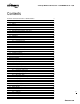
Limitorque MX DeviceNet Field Unit FCD LMENIM2328-00 – 11/05 Contents Declaration of DeviceNet Conformance – ODVA Certification Abbreviations 1 Introduction 1.1 Purpose 1.2 How to Use this Manual 1.3 User Safety 1.4 User Knowledge 1.5 DeviceNet System Capabilities and Features 1.5.1 General Specifications 2 System Components 2.1 Introduction 2.2 Hardware 2.2.1 Limitorque MX 2.2.2 DeviceNet Field Unit 2.2.3 Hardware interface 2.2.4 Network Cable 3 Installation and Configuration 3.
Limitorque MX DeviceNet Field Unit 4.5.1 Device Shutdown Message Configuration Confirmation 4.6.1 Checking Connections 4.6.2 View Settings 5 View DeviceNet Status 5.1 Checking the Normal Display 5.2 EDS File 6 Associated Documents 7 Troubleshooting 7.1 Workmanship 8 How to Order Parts 9 Regulatory Information 10 Wiring Diagram 4.
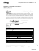
Limitorque MX DeviceNet Field Unit FCD LMENIM2328-00 – 11/05 Declaration of DeviceNet Conformance – ODVA Certification Declaration of Conformity to the DeviceNet™ Specification ODVA hereby issues this Declaration of Conformity to the DeviceNet™ Specification for the product(s) described below.
Limitorque MX DeviceNet Field Unit FCD LMENIM2328-00 – 11/05 Abbreviations CIP Common Industrial Protocol CAN Controller Area Network COS Change of State ODVA Open DeviceNet Vendor Association UCMM Unconnected Message Manager NV-RO Non-Volatile Read Only. Data is stored in non-volatile memory and can only be read. Data is stored during Power-Off. For DeviceNet Limitorque Interface this storage area is FLASH NV-RW Non-Volatile Read Write. Data is stored in non-volatile memory and can be read and write.
Limitorque MX DeviceNet Field Unit 1 Introduction 1.1 Purpose FCD LMENIM2328-00 – 11/05 This manual explains how to install and operate the Limitorque MX™/DeviceNet field unit (DNFU) and is to be used as an addendum to Bulletin LMENIM2306, Limitorque MX Installation and Operation Manual.
Limitorque MX DeviceNet Field Unit FCD LMENIM2328-00 – 11/05 a CAUTION: Directs the user’s attention to general precautions that, if not followed, could result in personal injury and/or equipment damage. NOTE: Highlights information critical to the user’s understanding of the actuator’s installation and operation. 1.4 User Knowledge It is recommended that the user read this manual in its entirety before the DeviceNet equipped actuator is installed and operated.
Limitorque MX DeviceNet Field Unit FCD LMENIM2328-00 – 11/05 Table 1.
Limitorque MX DeviceNet Field Unit 2 System Components 2.1 Introduction FCD LMENIM2328-00 – 11/05 This section gives an overview of the components used in the DeviceNet system. The field unit is installed in each MX actuator. The network cable connects the field unit to the network via the actuator terminal block. The network cable is connected to a host controller, typically a PLC. 2.
Limitorque MX DeviceNet Field Unit FCD LMENIM2328-00 – 11/05 The MX features include: • Non-intrusive setup • Separately sealed terminal chamber • Patented absolute encoder for valve position sensing (no battery required) • 32-character LCD for indication and calibration with configuration permitted in six languages. • Sophisticated electronic control, monitoring, and diagnostic capabilities with patented LimiGard™ technology 2.2.
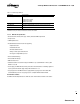
Limitorque MX DeviceNet Field Unit 2.2.3 FCD LMENIM2328-00 – 11/05 Hardware interface The DeviceNet Limitorque Interface is comprised of a minimum of one PCB with two interfaces - One for the DeviceNet Terminal Block connector and one for the SMT Main Board. Figure 2.3 gives an overview about the hardware. The microcontroller on the DeviceNet Limitorque Interface handles the DeviceNet protocol, stores the DeviceNet parameters in an EEPROM, and communicates with the SMT Main Board via SPI. Figure 2.
Limitorque MX DeviceNet Field Unit FCD LMENIM2328-00 – 11/05 Table 2.3 – Total cable length between repeaters or nodes: Network Size 125 KBPS 250 KBPS Thick Trunk Length 500 m (1,640 ft) 250 m (1,640 ft) Thin Trunk Length 100 m (328 ft) 100 m (328 ft) Flat Trunk Length 380 m (1,250 ft) 200 m (656 ft) Maximum Drop Length 6 m (20 ft) 6 m (20 ft) Cumulative Drop Length 156 m (512 ft) 78 m (256 ft) Note: Each actuator includes 0.60 meters of internal drop length. 3 Installation and Configuration 3.
Limitorque MX DeviceNet Field Unit FCD LMENIM2328-00 – 11/05 Figure 3.1 – Network cable connection to terminal block NOTE: Recommended DeviceNet cable is Belden 3084A or equal. 121 ohm, ¼ W +/-1% termination resistors must be connected at each segment end. Customer is required to connect wire between terminal 30 and chassis ground for surge protection. Preferred network wiring is to connect shield to terminal 48 for only one unit on each segment.
Limitorque MX DeviceNet Field Unit FCD LMENIM2328-00 – 11/05 NOTE: Ground each segment of the cabling at only one point to prevent ground loops, which can affect system performance. Verify the actuator is properly grounded. 6. Install jumper cable from terminal block pin 30 to earth ground or ground lug. 3.2 Installation Verification 3.2.
Limitorque MX DeviceNet Field Unit 4 FCD LMENIM2328-00 – 11/05 Object Model Diagram Figure 4.1 – Object Model of DeviceNet Limitorque Interface 4.1 Assembly Objects The Assembly Object binds attributes of multiple objects, which allows data to or from each object to be sent or received over a single connection. Assembly Objects can be used to bind input data or output data. The terms input and output are defined from the networks point of view.
Limitorque MX DeviceNet Field Unit FCD LMENIM2328-00 – 11/05 • An output is a signal produced at the PLC and sent to the actuator via the network. The user may select one output and one input instance. The default assembly objects are as follows: Polled input - 105, Polled output - 100, Bitstrobe - 107, COS - 109. Table 4.
Limitorque MX DeviceNet Field Unit FCD LMENIM2328-00 – 11/05 Table 4.4 – Output Assembly Instance 102 Class Assembly Object Instance ID Data Component Name ID Name 102 Output 3 100 Channel Interface Channel Interface Channel Interface Channel Interface 100 100 100 Attribute Instance ID ID Name 1 20 Ctrl_Status_Chan Data Type BYTE 1 9 DO_Position_Chan BYTE 1 21 DO_ESD_Poll_Cnxn BOOL 1 18 DO_Move_ Test_Chan BOOL Table 4.
Limitorque MX DeviceNet Field Unit FCD LMENIM2328-00 – 11/05 Table 4.
Limitorque MX DeviceNet Field Unit FCD LMENIM2328-00 – 11/05 Table 4.
Limitorque MX DeviceNet Field Unit 4.2.1 FCD LMENIM2328-00 – 11/05 DI_Position_and_Bus_Mode_Chan Table 4.12 Value Definition 0x21 0x22 0x24 0x28 0x30 0x41 0x42 0x44 0x48 0x50 0x81 0x82 0x84 0x88 0x90 Remote + Opened Remote + Closed Remote + Opening Remote + Closing Remote + Stop Local + Opened Local + Closed Local + Opening Local + Closing Local + Stop Stop + Opened Stop + Closed Stop + Opening Stop + Closing Stop + Stop 4.2.2 DI_Position_Chan Table 4.
Limitorque MX DeviceNet Field Unit FCD LMENIM2328-00 – 11/05 Table 4.
Limitorque MX DeviceNet Field Unit FCD LMENIM2328-00 – 11/05 Table 4.20 – Possible values of DI_Actuator_Alarms_Chan Value Definition 0x01 0x02 0x04 0x08 0x05 0x09 0x06 0x0A 0x0C Local ESD Active Remote ESD Active Open Inhibit Active Close Inhibit Active Local ESD Active + Open Inhibit Active Local ESD Active + Close Inhibit Active Remote ESD Active + Open Inhibit Active Remote ESD Active + Open Inhibit Active Open Inhibit Active + Close Inhibit Active 4.2.6 DI_Disc_User_Input_Chan Table 4.
Limitorque MX DeviceNet Field Unit FCD LMENIM2328-00 – 11/05 Table 4.25 Ctrl_Status_Chan DO_ESD_ Poll_Cnxn Attribute 20 Attribute 21 Bit 2 X 0 0 1 1 1 X 0 X 0 1 1 0 1 0 1 1 1 DO_ESD_ Bit_Strobe_Cnxn Enable_Broadcast_ ESD_Ctrl Attribute 22 Attribute 23 X X X 0 1 1 0 1 0 0 0 0 1 1 1 1 1 1 DO_ESD_ Chan 0 0 1 0 1 1 0 1 1 4.2.10 DO_Relay_Chan Table 4.
Limitorque MX DeviceNet Field Unit FCD LMENIM2328-00 – 11/05 4.2.14 DI_Actuator_Faults_3_Chan Table 4.30 Bit 7 – Bit 4 Bit 3 Bit 2 Bit 1 Reserved Low Battery Indication Interboard Power Fault Interboard Limiguard Fault Communication Fault 4.3 Bit 0 Channel Interface Object Table 4.
Limitorque MX DeviceNet Field Unit FCD LMENIM2328-00 – 11/05 Table 4.31 – Continued Data Type BOOL Attribute ID Access Rule Name 21 Get/Set (V-RW) DO_ESD_ Poll_Cnxn 22 Get/Set (V-RW) DO_ESD_ Bit_Strobe_Cnxn BOOL 23 Get/Set (NV-RW) Enable_ Broadcast_ ESD_Ctrl BOOL 4.
Limitorque MX DeviceNet Field Unit FCD LMENIM2328-00 – 11/05 Table 4.
Limitorque MX DeviceNet Field Unit FCD LMENIM2328-00 – 11/05 Table 4.
Limitorque MX DeviceNet Field Unit FCD LMENIM2328-00 – 11/05 Table 4.34 Bit 15 - 11 Bit 10 - 9 Bit 3 Unused Scaling 0 = 0 – 100 1 = 0 – 255 2 = 0 -4095 3 = Reserved Unused 4.4.1 Identity Object Instance Attributes Table 4.
Limitorque MX DeviceNet Field Unit FCD LMENIM2328-00 – 11/05 • International Product Name (Attribute ID 13) • Semaphore (Attribute ID 14) are not supported by DeviceNet Limitorque Interface. Some of the instance attributes do not have any external interfaces, these values are managed directly in the DeviceNet Slave Software. Note 1: The Vendor ID is managed by the ODVA. Flowserve has already obtained a valid Vendor ID.
Limitorque MX DeviceNet Field Unit FailedTests DeviceNet Limitorque Interface Activated Deactivated SMT Main Board SMT Main Board Minor Fault SMT Main Board Major Recoverable Fault 4.4.3 One or more of the following errors have been detected during self-test of the DeviceNet Limitorque Interface e.g. - FLASH Checksum Error - RAM Memory Test Error Is_Active-Flag is TRUE Is_Active-Flag is FALSE OR EEPROM Checksum Error Conditions that can cause this event are e.g.
Limitorque MX DeviceNet Field Unit FCD LMENIM2328-00 – 11/05 Note 1: At boot time of the DeviceNet Limitorque Interface the values stored in non-volatile memory are used. The SMT Main Board could at any time send new values via SPI. The other instance attributes do not have any external interfaces, these values are managed in the protocol stack of the DeviceNet Slave Software. The further optional attribute Quick Connect (Attribute ID 10) is not supported by DeviceNet Limitorque Interface. 4.4.
Limitorque MX DeviceNet Field Unit 4.4.5 FCD LMENIM2328-00 – 11/05 Discrete Output Point Object – Class ID 9 (09hex) The Discrete Output Point Object is used to provide an interface to a subset of the discrete outputs of the MX. The implementation of this object follows the guidelines of [1] Chapter 5‑10. The Discrete Output Point Object is implemented with 7 instances described in Table 3.1‑29, so that each of the selected discrete outputs of the MX is connected to one instance.
Limitorque MX DeviceNet Field Unit FCD LMENIM2328-00 – 11/05 Table 4.41 – Analog Output Point Object Instance ID Channel Interface Object Source 1 Instance Attribute 19 AO_Analog_Output_CHAN 4.4.8 MAC ID The MX-DeviceNet unit may have the MAC ID set by one of two different methods. The first is the MX LCD display. The other is via the DeviceNet bus. 4.4.9 Baud Rate The MX-DeviceNet unit may have the Baud Rate set by one of two different methods. The first is the MX LCS display.
Limitorque MX DeviceNet Field Unit FCD LMENIM2328-00 – 11/05 The Device Heartbeat Message is triggered by the Identity Object Instance Attribute Heartbeat Interval (Attribute ID 10). For this, the Heartbeat Interval has to be set to the time interval of the Device Heartbeat Message in seconds. 4.5.1 Device Shutdown Message The DeviceNet Limitorque Interface supports the Device Shutdown Message. The DeviceNet Limitorque Interface produces this message when it transitions to the offline state. Table 4.
Limitorque MX DeviceNet Field Unit 4.6.2 FCD LMENIM2328-00 – 11/05 View Settings Refer to Bulletin LMAIM1306/2306, MX Installation and Operation Manual to access the “VIEW SETTINGS” menu. Verify the settings as follows: 5 View DeviceNet Status Figure 5.
Limitorque MX DeviceNet Field Unit FCD LMENIM2328-00 – 11/05 • The device has not completed the self test yet. • The device may not be powered, look at Module Status Display. • "ONLINE" = Device is on-line but has no connections in the established state. • The device has passed the SELF test, is on-line, bus has no established connections to other nodes. • For a Group 2 Only device it means that this device is not allocated to a master.
Limitorque MX DeviceNet Field Unit 5.2 FCD LMENIM2328-00 – 11/05 EDS File The DeviceNet Limitorque Interface can be configured using Rockwell Automation RSNetWorx for DeviceNet and an EDS-File. Table 5.1 shows a list of all supported parameters. Table 5.1 Parameter List Parameter No. 1-23 24-78 79 80 81 Access Path to Object Read/Write resp. Read Only Read/Write resp.
Limitorque MX DeviceNet Field Unit FCD LMENIM2328-00 – 11/05 7. CLOSE INHIBIT must be configured for desired function and properly wired. 8. Remote control is not selected if not in use. Properly wired if selected. 9. Confirm there are no duplicate DeviceNet addresses. 10. Confirm that ground is at one end only per network cable segment. 11. Confirm protocol, baud rate Main power supply must be within +/- 10% of nominal unit power rating at all times. Refer to nameplate for voltage.
Limitorque MX DeviceNet Field Unit FCD LMENIM2328-00 – 11/05 • Do not touch the surface of the printed circuit board, the connectors, or the components with conductive devices or with your hands. • Always place the component or board into an anti-static protective bag for transportation or storage. • Transport all static-sensitive components only in static-shielding carriers or packages. Place static awareness labels on all components to prevent removal from static-shielding container during transit.
Limitorque MX DeviceNet Field Unit 10 FCD LMENIM2328-00 – 11/05 Wiring Diagram Figure 10.
Limitorque MX DeviceNet Field Unit 42 FCD LMENIM2328-00 – 11/05
Limitorque MX DeviceNet Field Unit FCD LMENIM2328-00 – 11/05 43 flowserve.
United States Flowserve Corporation Flow Control Limitorque Actuation Systems 5114 Woodall Road P.O. Box 11318 Lynchburg, VA 24506-1318 Telephone: 1 434 528 4400 Telefax: 1 434 845 9736 FCD LMENIM2328-00 Printed in USA. To find your local Flowserve representative: For more information about Flowserve Corporation, visit www.flowserve.com or call USA 1 800 225 6989 Flowserve Corporation has established industry leadership in the design and manufacture of its products.