
User Manual

Third Millennium Systems Limited, 18/19 Torfaen Business Centre Panteg Way New Inn.
Pontypool. NP4 0LS.
T 0044 (0) 1495 751 992. F 0044 (0) 1495 757 448
Email info@third-millennnium-sys.com
Web www.third-millennium-sys.com
Third Millennium TM5 Series
Installation Instructions
Page 2 of 2
December 2006
Introduction:
The TM5 proximity keypad reader provides a convenient and easy-to-use means of transmitting
RFID proximity card data and PIN data to an access control panel. The TM5 is quick and easy to
install on any flat surface using the stainless steel fixing screws and wall plugs supplied, it can
even be mounted direct to metal surfaces with no significant loss of read range. The durable push
button keypad is back-lit to allow for operation at night, and a beep is emitted on every button
press.
A back-box is also available if surface-mount conduit cable entry is required. An optional buzzer
(110+ dB) can be fitted in the back-box for applications where there are high levels of background
noise.
TM5 proximity keypad readers are available in many different output formats allowing interface
with virtually all access control systems. Please ensure that the correct format is requested at time
of order.
Installation:
The TM5 is designed to be mounted flush to the wall surface. Use the reader housing to mark out the position of the fixing screws,
drill two holes suitable for the fixing screws and wall material. When drilling standard brick material a 6 mm drill should be used. If
mounting on sheet material, glass, metal etc. the mounting arrangements will need to be modified to suit. Drill a hole roughly mid-
way between the two mounting holes for the connection cable.
Operation:
When power is applied to the reader, the red LED will light and the beeper will sound to
indicate the reader is fully functional. For optimum read range the card should be
presented face-on to the reader. Typical read ranges are 15 cm when used with ISO
proximity cards, and 8 cm with proximity keyfobs.
Cabling:
It is recommended that Belden 9536 screened cable, or equivalent, is used between
reader and control panel. The recommended maximum distance between reader and
control panel is 100 metres. This is dependant upon type of cable used and the electrical
environment present. ALWAYS VERIFY THAT THE CABLING DISTANCE AND
ROUTING IS SUITABLE.
Current:
120mA – 250mA Typical, dependant on mode of operation.
Environmental:
TM5 Series proximity keypad readers have been designed for both internal and external applications in severe weather conditions.
The electronics are fully encapsulated in the UV stable compound polycarbonate housing, ensuring that the readers are both
weather proof and virtually unbreakable.
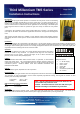
1 2 3 4 5 6 7
Wiring Connections
1 5 – 16 Vdc Supply
2 Data 1 / Clock
3 Data 0 / Data
4 Green LED
5 Red LED
6 Card Present (C&D Only)
7 0V / Ground
Note – with the optional buzzer fitted in the back box, the
rear conduit entry cannot be used.
Caution – the back-box buzzer emits 110+ dB and may be
harmful to hearing if used without ear
protection.
Temperature -20 C to + 60 C
Humidity 100% RHNC
Optional back-box buzzer connections:
Red 5 – 16 Vdc
Black 0 V / Ground
Grounding:
It is recommended that the proximity reader, control panel and power supply unit have a common ground. The screen of the
Belden 9536 cable should be firmly connected to the power supply grounded chassis to prevent ground loops.