Build-in cooking hob Topline hybrid glass hobs SHB981XXZ Series dual fuel For use with mains electricity and Universal LPG User and installation instructions Please read and keep for future reference For use in Australia THETFORD AUSTRALIA PTY LTD 41 LARA WAY CAMPBELLFIELD VIC TEL: 03 9358 0700 FAX: 03 9357 7060 www.thetford-europe.
CAUTION • Appliance and accessible parts become hot during use. Avoid touching the heating elements or pan supports when in use. • The use of a gas cooking appliance results in the production of heat, moisture and products of combustion in the room in which it is installed. Ensure that the kitchen is well ventilated especially when the appliance is in use. Keep natural ventilation holes open or install a mechanical ventilation device (mechanical extractor hood).
CAUTION • Do not modify this appliance. Do not make any adjustments unless such work is carried out by authorized personnel, the manufacturer or their representative. No parts other than those supplied by the manufacturer shall be used on this appliance. • Do not allow cooking vessels to overlap the edges of the appliance – use the correct sizes of pans and position them centrally over the burners.
INTRODUCTION This appliance is designed for cooking foods and any other use is incorrect and may be dangerous. Failure to install the appliance correctly or improper use will invalidate any warranty or liability claims. This appliance must only be installed by a qualified installer or engineer in accordance with the relevant local and national regulations in force. Failure to install the appliance correctly could invalidate any warranty or liability claims and lead to prosecution.
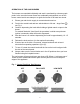
OPERATION OF THE GAS BURNERS The burners are controlled individually and each is monitored by a thermocouple probe. In the event the burner flames are accidentally extinguished, turn off the burner control and do not attempt to re-ignite the burner for at least one minute. 1. Ensure gas and electric supply is connected and turned on. 2. Push in the control knob and turn anticlockwise to full rate – large flame ( ), see Fig 1. 3.
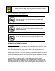
• • Avoid old or miss-shaped pans as these may cause instability. Using excessively large pans may reduce performance or cause damage. GLASS SYMBOL DESCRIPTIONS Do not remove the pan support and enclose the burner with a wok stand as this will concentrate and deflect heat onto the hotplate Do not place anything, e.g.
OPERATION OF THE INDUCTION HOB The induction heating zone is marked with a circular dotted line with the symbol ‘IN’ at the centre. Please ensure, regardless of pan type (stainless, enameled steel, cast iron, etc) the pan base is smooth and flat to avoid the risk of scratching the glass. Never slide the pan across the glass surface, lift the pan to avoid scratches. We recommend pans with a base diameter of Ø135mm to Ø220mm for the induction heating zone.
Switching On: Place a suitable pan containing food or water on the induction heating zone. The induction heater is switched on when the control knob is rotated clockwise from power level ‘0’ position to any higher position. When the heater is activated the red LED light is illuminated to indicate the power setting from ‘1’, lowest power, to ‘9’ maximum power. A graduated display around the control knob also indicates the increasing power setting.
Automatic Heat-up: This function allows rapid heat up of the induction zone, with automatic reduction to a preset level once the desired temperature is reached. To activate, with a suitable pan in position and the control set to ‘0’, rotate the control knob anti-clockwise briefly until ‘A’ is shown in the LED display, then rotate the knob immediately clockwise to the desired pre-set power level.
LED Indication of Fault or Error Codes. If the following Symbol┌┘ or letter E is displayed followed by a number, this indicates that the appliance has developed an internal technical fault. Switch off the appliance at the power supply. If the fault indication does not clear when mains power is restored then it cannot be rectified by the user. Switch off the power and consult your installer or qualified Service Agent. Cooling Fan.
CARE AND MAINTENANCE Cleaning the Hob Check that the appliance is cool before cleaning and switch off the electricity supply. For routine cleaning of the glass surface use a ceramic cleaning cream and clean cloth or paper towel. After cleaning, wipe dry with a dry paper towel. If the glass surface becomes discoloured due to cooking deposits and for cleaning more stubborn stains, use a ceramic hob scraper.
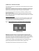
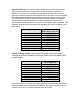
Fig 1 - Appliance Rating and Overall Dimensions Appliance type SERIES 981 SHB981XXZ Appliance overall dimensions Gas Burner Ratings Auxiliary Burner Semi-Rapid Burner Total Gas Input (∑) MJ/hr / kW Induction Hob Power Consumption L 500mm D 380mm H 70mm MJ/hr kW Injector 3.8 1.05 0.52mm 5.9 1.64 0.67mm 9.70 2.69 230 – 240V AC 50 Hz kW Max Amps 1.4 6 Amps Spark Ignition 12 Volt DC Gas; Universal LPG – 2.
INSTALLATION Fig 2a Worktop Cut-Out Details SHB981XXZ Series The worktop cut-out and fixing holes must be prepared to the dimensions shown below.
INSTALLATION Regulations and Standards In the interest of safety, it is a legal requirement that all gas and electrical appliances are only installed and serviced by an approved competent person, in accordance with the local and National standards in force. Failure to install the appliance correctly will invalidate any warranty or liability claims and may lead to prosecution. Particular attention shall be given to the requirements regarding ventilation in AS/NZS 5601.
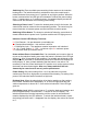
INSTALLATION Fig 4 - Cross Section View of Appliance Mounted in a Worktop 30mm Minimum air gap from lowest part under the hob. Non – combustible material. Vent – 8mm x 100mm minimum. Gas dispersal hole (Ø12mm Minimum, Ø25mm Maximum). Ventilation This appliance is suitable for installation into Holiday Homes, Touring Caravans and Boats. In all cases the national standards with regard to ventilation for the particular vehicle into which the appliance is to be installed must be adhered to. AS/NZS 5601.
INSTALLATION Position A cutout should be prepared as shown in the enclosed diagrams – see Fig. 2 and Fig.2a for model cutout details. We recommend the underside of the hob be shielded, particularly if this area is to be used for storage or the installation of another appliance. The shield should be fabricated from non-combustible material, but if the enclosure is manufactured from combustible material there should be a minimum air gap of 30mm between lowest part under hob and the shield, see Fig 4.
INSTALLATION This appliance must be positioned free from draughts, which may affect the combustion, and in a manner that will prevent the accumulation of unburnt gas. When in use ensure that air vents are not inadvertently blocked or shut off. If other appliance/s are located below the hob we recommend conducting a temperature verification test to confirm any rise in temperature of the cabinet materials are within allowable limits and meet requirements specified in AS 45512008.
INSTALLATION Electrical Connection Models fitted with power cord only (See Fig.6 Mains Wiring Diagram). These appliances are supplied with a double insulated cord, type 227 IEC 53, HO5V V-F, which is suitable for use up to 10 amps. This should be connected to a suitable double pole switched mains supply, with 3mm minimum contact separation at all poles. Ensure that all electrical cables and wires are routed well clear of any heat source, including this appliance.
INSTALLATION Fault Indication Error or Fault codes in the Induction system are displayed on the LED display by flashing ‘E’ or ‘┌┘’ symbol, followed by a number. In the event that the induction unit detects an error or internal fault other than ‘H’ residual heat, contact the Thetford Service Centre. SERVICING Do not modify this appliance. All servicing must be carried out by an approved competent person.
SERVICING Hob burner injector removal/replacement. Unclip the enameled pan rest from the stainless steel burner boss and lift off. Remove the screw in the burner cap and lift off the burner cap and skirt / flame spreader. With a 7mm A/F socket, unscrew the injector from the bottom of the burner mixing tube. Replace/refit using the reverse of the above procedure. Thermocouple removal/replacement Disconnect gas and electrical supplies and remove the rear cover as above.
FAULT DIAGNOSIS GAS OPERATION FAULT OBSERVED CAUSE SOLUTION Burner will not adjust (continuously on low or high flame setting) Gas pressure Blocked jet Control tap fault Check gas pressure correct Clear blockage from jet and check the jet size Inspect / test the control tap Burner causes soot deposits Gas pressure Burner flame lift Gas Pressure Burner – no Spark Ignition Power supply Poor connection Spark generator Burner will not remain lit Thermocouple failure.
Fig 6.