BUILD-IN COOKING HOB FOR USE WITH UNIVERSAL LPG ONLY TOPLINE SURFACE-MOUNTED GLASS HOBS USER AND INSTALLATION INSTRUCTIONS Please read thoroughly and keep for future INS1019Z – Issue 2 • This appliance must be installed by an authorised person. • Only use this appliance in a well ventilated area.
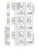
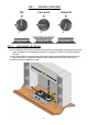
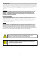
FIG. 1 OFF FIG. 2 CONTROL POSITIONS FULL RATE LOW RATE APPLIANCE LOCATION (A) Any adjoining wall surface situated within 200mm from the edge of any hob burner must have a suitable non-combustible material for a height of 150mm for the entire length of the hob. (B) Any combustible construction above the hob must be at least 600mm above the top of the burner and no construction shall be within 450mm above the top of the burner.
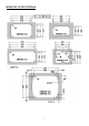
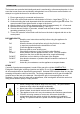
WORKTOP CUTOUT DETAILS 7
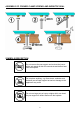
ASSEMBLY OF CORNER CLAMP SCREWS AND WORKTOP SEAL SYMBOLS DESCRIPTION Do not remove the pan support and enclose the burner with a wok stand as this will concentrate and deflect heat onto the hotplate Do not place anything, e.g.
INTRODUCTION In your own interest of safety, gas appliances should be installed by competent persons. Failure to install the appliance correctly could invalidate any warranty or liability claims. This appliance shall be installed in accordance with the manufacturer’s installation instructions, local gas fitting regulations, municipal building codes, AS/NZS5601 and any other relevant statutory regulations.
OPERATION The burners are controlled individually and each is monitored by a thermocouple probe. In the event the burner flames are accidentally extinguished, turn off the burner control and do not attempt to re-ignite the burner for at least one minute. 1. Ensure gas supply is connected and turned on. 2. Push in the control knob and turn anticlockwise to full rate – large flame ( ) Fig. 1. 3. Continue holding the knob depressed whilst the automatic ignition lights the burner.
MAINTENANCE We recommend an annual service by an authorised service agent to maintain efficient appliance performance. This appliance needs little maintenance other than cleaning. All parts should be cleaned using warm soapy water. Do not use abrasive cleaners, steel wool or cleansing powders. When cleaning the burner ring it is essential to ensure that the holes do not become blocked. The control knobs are a push fit and can be removed for cleaning.
INSTALLATION Connection A ¼ BSP female connection is provided on the underside of the appliance. It is recommended that the appliance be connected by copper tubing; a rubber or hose connection must not be used. After connection the appliance must be tested for soundness. The gas inlet must be accessible with the appliance installed to ensure installation in accordance with AS/NZS5601. This appliance is suitable for use on: Universal LP Gas Only 2.75 kPa.
SERVICING 2. Hob Burner Gas valve removal/replacement • Shut off gas supply and disconnect gas supply pipe from the unit. • Remove the hob from the bench top. • Remove the appropriate control knob by pulling up. • From underside of hob, disconnect appropriate thermocouple at the gas valve. • Unscrew the appropriate gas supply pipe nut. • Remove the appropriate gas valve clamp by unscrewing the two screws. • Unscrew the gas valve retaining nut. • Remove the gas valve. • Replace the tap and gasket.
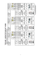
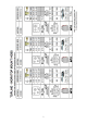
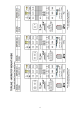
FAULT DIAGNOSIS FAULT CAUSE Burner sooting. Control tap Gas pressure Burner will not adjust (continuous on low or high flame). SOLUTION Gas pressure Blocked jet Burner – no Spark Ignition Power supply Poor connection Spark generator Discoloured pan rest Not a fault Burner will not remain lit Thermocouple failure. Blocked jet Check gas pressure correct Clear blockage from jet. Check jet size correct Inspect/test control tap Check pressure, low pressure is the cause of soot deposits.