Build-In Cooking Hob SHB353XXZ Series Hobs SCU353XXXZ Series Combination Hobs For use with Universal LPG User and installation instructions Please read and keep for future reference For use in Australia INS 1024Z – Issue 0 - English Original Instructions THETFORD AUSTRALIA PTY LTD 41 LARA WAY CAMPBELLFIELD VIC TEL: 03 9358 0700 FAX: 03 9357 7060 www.thetford-europe.
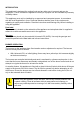
CAUTION • Appliance and accessible parts become hot during use. Avoid touching the heating elements or pan supports. • The use of a gas cooking appliance results in the production of heat, moisture and products of combustion in the room in which it is installed. Ensure that the kitchen is well ventilated especially when the appliance is in use. Keep natural ventilation holes open or install a mechanical ventilation device (mechanical extractor hood).
CAUTION • Do not allow cooking vessels to overlap the edges of the appliance – use the correct sizes of pans and position them centrally over the burners. • Do not use harsh abrasive cleaners or sharp metal scrapers to clean the glass since they can scratch the surface, which may result in shattering of the glass. • Do not use steam cleaners or pressure washers to clean the appliance. Refer to cleaning and maintenance instructions. • This appliance is for cooking purposes only.
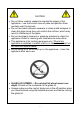
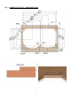
APPLIANCE DIMENSIONS AND SPECIFICATIONS APPLIANCE SHB353XXZ SERIES H W D (mm) (mm) (mm) 101 660 APPLIANCE 410 160 Gas Input & Injector Size SHB353XXZ SERIES ∑ Qn kW MJ/hr 1.0 3.6 1.75 6.3 2.5 9.0 5.25 SCU353XXXZ SERIES H W D (mm) (mm) (mm) 980 Gas Input & Injector Size SCU353XXXZ SERIES mm 0.52 0.67 0.82 18.9 ∑ Qn Spark ignition Spark ignition Appliance Weight Appliance Weight 8.5 kg Gas category – Universal LPG Only Universal LPG 2.75 kPa / 27.5 mbar 4 kW 1.0 1.75 2.5 MJ/hr 3.6 6.3 9.
Fig.
Fig.
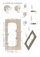
Fig. 3 - SURFACE MOUNT FIXING – SHB & SCU 353 SERIES EDGE DETAIL Fix the hob centrally in the cut-out to maintain a 2-3mm air gap to the worktop. 1 3 5 7 Surface mounting bezel Glass Lid Bump Stop Worktop 2 4 6 Pressing Screw fixing cap Wood Screw Fig. 4 – MINIMUM DISTANCE TO COMBUSTIBLE MATERIALS For SHB353 & SCU353 Series, the minimum permitted distances to combustible materials are as shown below. A= 200mm minimum unless protected by a non-combustible heat barrier.
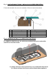
Fig. 5 – Air Gap and Gas Dispersal Hole A = 58mm Air gap beneath hob pressing. B = Gas dispersal hole. Min Ø 12mm, max Ø 25mm, with baffle & grille, venting to outside. Fig. 6 – Control Positions OFF FULL RATE LOW RATE Fig. 7 – Minimum and Maximum Pan Sizes • • • • The minimum permitted pan sizes are Ø100mm for the auxiliary burner, Ø120mm for the semi-rapid burner and Ø150mm for the rapid burner. The maximum recommended pan sizes are as shown below.
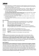
INTRODUCTION This appliance is designed for cooking foods and any other use is incorrect and may be dangerous. Failure to install the appliance correctly or improper use will invalidate any warranty or liability claims. This appliance must only be installed by an approved and competent person, in accordance with the local Regulations in force. Particular attention shall be given to the requirements regarding air supply and ventilation.
OPERATION Hob burners 1. Ensure gas supply is connected and turned on and the glass lid to the hob is fully open before using the appliance. For combination units the separate glass lid to the sink bowl may be left closed whilst the hob is in use. 2. Push in the control knob and turn anticlockwise to full rate – large flame ( ), see Fig 6. 3. Continue depressing the knob whilst holding a lighted match or taper to the burner.
INSTALLATION Regulations and Standards Read the instructions before installing this appliance and comply with the cautions and warnings section on Page 2 & 3 of this manual. Gas appliances must only be installed and serviced by an approved and competent person. Failure to install the appliance correctly could invalidate any warranty or liability claims and may lead to prosecution. Prior to connection ensure the local conditions for gas type and gas pressure match the appliance specification.
INSTALLATION Care should be taken to position the appliance centrally in the worktop cut-out to ensure an air gap is maintained between the edges of the appliance and the sides of the cut-out. The appliance may then be fixed in position with screws - see Fig. 3. Make sure the appliance is level and correctly positioned in the aperture before fixing in place.
INSTALLATION Electrical Connection The spark ignition generator must only be connected to a suitable 12V DC battery. Sheathed spade connectors should be used to connect the spark generator to the power supply. To ensure correct operation observe the following installation requirements: • • • • • • Build the appliance into a self-contained cabinet which is not connected to externally vented chambers in adjacent furniture, other than the correct size gas dispersal hole.
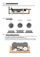
Hob burner injector removal/replacement. Lift off the appropriate pan rest to release it from the rubber bushes. Remove the screw in the burner cap and lift off the burner cap and skirt / flame spreader. With a 7mm A/F socket, unscrew the injector from the bottom of the burner mixing tube. Replace/refit using the reverse of the above procedure. Thermocouple removal/replacement Shut off gas supply and disconnect gas supply pipe from the unit. Remove the hob from the worktop as above.
FAULT DIAGNOSIS FAULT CAUSE Burner will not adjust (continuous on low or high flame). SOLUTION Gas pressure Blocked jet Check gas pressure correct Clear blockage from jet. Check jet size correct Inspect/test control tap Check pressure, low pressure is the cause of sooting. Check power supply Check all connections Test spark generator Earth leakage due to damaged wire Test & replace thermocouple if required Check thermocouple in flame path Clear jet blockage Control tap Burner sooting.