
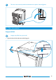
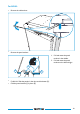
Install Guide

C
$-*$'$"0""-
240VAC
12VDC-HC +
12VDC-HC COM
AC heater
N
L
DC heater
Fuse 25A
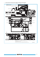
WIRING DIAGRAM
WIRING PICTORIAL
691718
MODEL N4141-N4142-N4175 TYPE AUS
Power Control Module
Thermistor
Display Module
Divider heater
(Double door only)
Burner Control
Module
Spark electrode
Solenoid Gas valve
12VDC heater
240VAC heater
240VAC powercord
Engine Run
12VDC - LC
12VDC - HC
+-+-
Fuse 25A
Fuse 2A
Earth tab
Power Source
Level
Div. Heat.
12VDC-LC +
12VDC-LC COM
Fuse 2A
Reseable fuse
1.1A
Solenoid gas valve
Spark electrode
Fuse 1.1A
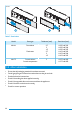
BCM
μC
5V
PSU
to
DM
Comm.
+12V-LC
+5V-DM
GND
PCM
Fan-1
Fan-Int
Fan-2
MODEL N4141-N4142-N4175 TYPE AUS
Fuse 1.0A
Fuse 1A
3V3
PSU
μC
to
PCM
Comm.
+12V-LC
+5V-DM
GND
4xA
B
10/11xC
D
E
μC
5V
PSU
to
PCM
Comm.
+12V-LC
+5V-DM
GND
4xF
B
11xG
D
E
DM-LED+
DM-LCD
A) Push buons: Power, Back, Mode/Enter, Next
B) Reed switch
C) LED’s: auto mode, 3x Source, 5x Temperature, divider heater
D) Interior lights
E) Divider heater (double door only)
F) Push buon Power and 3x touch switch: source, temperature, divider heater
G) LCD symbols: auto mode, 3x source, 5x temperature, divider heater, 2 digit error code
Fan-Int Fan-2
Fan-1
Thermoswitch-1
Thermoswitch-2
Thermoswitch-1
Thermoswitch-2