
Installation Guide

Rev.1.12.09.10 6
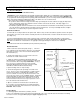
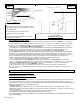
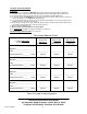
Figure 4
Thermostat Wiring Diagrams
***Refer to Instructions that came with your specific thermostat***
Installation Methods:
®
Glued-Down Wood Method #2-1
Setting Material: Use only wood flooring adhesive approved by the
flooring material manufacturer below and above the WarmFlex
®
.
Trowel Size: 3/16” x 3/16” Square-notch or U-notch
Sub-floor Requirements:
• Maximum 1/4” variance in 10’.
• Must be properly prepared per NWFA specifications.
• All cracks in excess of 1/16” must be filled.
• Surface must be clean, dry and free of contaminants and sealers.
Installing WarmFlex
®
1. Lay out the WarmFlex .
2. Where necessary, use unheated padding to fill in the gaps. Duct tape all seams. Do not tape over heating wire.
3. Pull back the WarmFlex .
4. Apply adhesive to the subfloor as per manufacturer’s instructions.
5. Lay the WarmFlex back into the adhesive.
6. Immediately (within 10 minutes) roll the WarmFlex with a 35 lb roller in diagonal directions.
7. Do not walk on the rolled areas.
8. Seams should be butted together without overlaps.
9. Allow set time as per adhesive manufacturer’s instructions.
WarmFlex™
Typical Electrical
Wiring Diagram
Programmable
Thermostat
Wiring Diagram
Thermostat with
Contactor/Relay
All electrical work
must be done by
a qualified, licensed
electrician in
accordance with
local building and
electrical codes,
and the National
Electrical Code
(NEC), especially
Article 424, Part
IX of the NEC,
ANSI/NFPA 70
and Section 62 of
CEC Part I.
Note: if installing
a programmable
thermostat, do not
install an external
timer. The timer
will disrupt the
programming. If
interfacing with a
building energy
management
system, use a
manual thermostat.
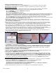
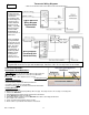
Concrete Slab Subfloor
ThermoFlex™
ThermoFlex™
* If installing 240V heating mats, the lead wires are black (line) and red (line) - not white (neutral). Thermosoft’s
programmable thermostat accepts dual 120/240V input. Otherwise, make sure all components are rated 240V.
*
*
*
*
*
Underlayment pad