
Installation Guide

Rev.1.12.09.10 5
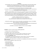
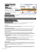
Figure 2
Thermostat
WarmFlex
®
WarmFlex
®
WarmFlex
®
butt together and
duct tape seams
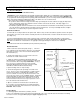
Sensor Wire Location
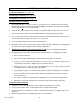
Figure 3
Leave 1” space from the wall to run lead wires. Small
gaps around the perimeter do not need to be covered
by an underlayment.
* A contactor/relay may be required for large
installations. Consult an electrician.
** Sensor can be run down the wall or in a separate
conduit from the power leads.
Locate thermostat sensor probe equally spaced between two heating wires.
Tape wire in place.
Do not tape over sensor.
1-E Final Wiring & Connections
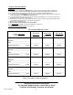
1. After installing your floor, use the ohmmeter to record the final resistance measurement of WarmFlex . The resistance
must be within ±10% of the factory recorded resistance. If not, call our customer service number for assistance. Damage
may have occurred during floor installation. Keep a record of all three resistance measures as they will be needed for
warranty purposes. See Resistance Measures Chart, page 9.
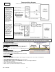
2. Install the floor sensing thermostat in the 4” square electrical box according to the installation instructions provided with
the thermostat. Connect the power mat leads, floor sensor, and power supply wiring as shown in the thermostat
instructions and as diagramed on the back of the thermostat. For wiring diagrams, see Figure 4, page 6.
3. Route WarmFlex lead wires up through the electrical conduit and into the 4” square thermostat box. Wire the leads in
parallel (not series) 120V: black-black (line) and white-white (neutral); 240V black-black (line) and red-red (line). Then
wire a short “pig-tail” (of correctly sized wire for the load) over to the thermostat. The number of conductors per connection
must not exceed the amperage rating of the circuit or local or national codes. Field wiring must be 14 gauge or as
otherwise appropriate for the Amp load of the installation as specified by local and national codes.
4. Use a 1-gang mud ring to mount the thermostat if using a 4” electrical box.
5. Indicate which circuits supply the WarmFlex and retain the ETL labels for each WarmFlex mat in a convenient
location, ie., taped to the circuit breaker box, for reference by the electrical inspector or homeowner. Leave one ETL label
attached to the WarmFlex mat. Attached warning label #1 in a convenient location e.g., inside of breaker panel, or
thermostat control door in the room where WarmFlex is installed.
6. After all thermostatic controls are installed, power up the system to briefly test operation of all components.
7. Refer to instructions provided with the thermostatic controls for proper setting. Keep instructions in a safe place for
future reference.
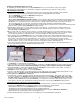
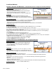
2. GLUED-DOWN ENGINEERED AND SOLID WOOD FLOORS
2-A Electrical Rough-In: See section 1-A.
2-B Planning & Preparation: See section 1-B.
2-C WarmFlex™ Installation
Approved Surfaces for Applications: Plywood, wood, hardboard underlayment, association grade particleboard, concrete
above grade in the absence of excessive moisture and/or excessive alkali, and well-bonded VCT* and sheet vinyl* (non-
embossed and non-cushioned). Sub-floor must meet NWFA (National Hardwood Flooring Association) and local building code
standards for quality, thickness and maximum deflection.
*Sheet Vinyl or VCT:
• If possible, remove the old sheet vinyl or VCT. It is almost always better to install over the original sub-floor surface.
• Wood sub-floors that are structurally suitable for vinyl, may not be suitable for ceramic tile or wood floors. Double-check the
sub-floor requirements.
• If not removed, the vinyl must be well adhered to the sub-floor throughout the entire floor.
• If installing on top of vinyl, make sure the adhesive is approved for use on vinyl.
• Allow additional drying or “set” time (at least twice the manufacturer’s recommendation) for the setting material used in each
phase of the installation.
ThermoFlex
Sensor
probe
Sensor wire
Heating
wire
Tape
*Relay if
required
conduit
Sensor