
Installation Guide

Rev.1.12.09.10 4
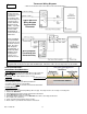
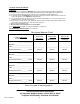
Installing a Power Module (Relay / Contactor)
12. Depending on the Amp requirements of multiple WarmFlex™ mats, a power module or relay may be required.
Call Thermosoft Technical Support or consult with an electrician to determine the type and size of relay required.
1-B Planning & Preparation
1. Plan the heated area of the floor so that the desired traffic areas can be heated with a combination of the available
WarmFlex sizes. When planning your heated floor area, keep the following important points in mind:
• Do not cut WarmFlex or cut or pierce WarmFlex’s heating wires.
• Do not overlap WarmFlex.
• Do not duct tape over WarmFlex’s heating wires.
• Do not power 120V WarmFlexs with 240 Volt power. Power 120V mats with 120V power and 240V mats with 240V power.
• Lead wires should run along the end of the mats to the nearest wall and electrical junction box. Check local and national codes
regarding the use of conduit from the floor to the junction box. A qualified electrician must make all electrical connections.
• Do not run lead wires over or under mats. Run lead wires between mats and between underlayment padding.
• Do not install WarmFlex heaters under cabinets, built-ins or furniture with a solid surface base. Excessive heat will accumulate
under these items and may damage WarmFlex’s heating elements.
2. With all approved floor types, be sure the subfloor surface is clean and dry*. The floor must be completely swept of all
debris including all nails, dirt, wood and other construction debris. Make absolutely sure there are no objects on the floor
that might damage the WarmFlex wires.
*Where concrete slabs are subject to excessive moisture, a calcium chloride moisture test is recommended. Vapor emission
readings in excess of 3 lbs. per 1,000 square feet in 24 hours may require additional protection such as a concrete sealant
or 6 mil (.006”) polyethylene sheeting (vapor barrier). If in doubt, install 6 mil (.006”) vapor barrier on the slab.
3. Before starting, remove the WarmFlex from the box. Attach both lead wires (120V: black & white; 240V: black & red) to a
high quality digital ohmmeter to measure the resistance. Compare the resistance you measured to the resistance recorded
by the factory on the label attached to the heating mats. If the resistance is not within ±10% of the factory recorded
resistance, call our customer service number for assistance. Damage may have occurred during shipping. Do not proceed
with the installation. Keep a record of resistance measures as they will be needed for warranty purposes.
4. Leave the factory labels attached to the heating mats and the lead wires for later inspection. Save warning label #1 and
place it inside the breaker panel to identify the radiant flooring circuit.
1-C WarmFlex™ Installation
1. Lay flooring underlayment pad on subfloor according to the flooring manufacturer’s instructions.
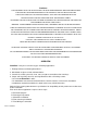
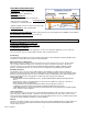
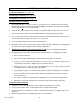
1. Lay WarmFlex over underlayment pad. (Photo 1)
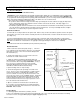
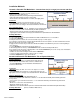
2. Layout lead wires so they run to the nearest wall with an electrical box. (See Fig. 2 page 5.) Connections will be made later.
(Photo 2) Cut a strip out of the underlayment padding if necessary to lay the lead wires flat between the padding.
3. Allow approximately 1” of floor space between the wall and WarmFlex to run the lead wires to the conduit. Use strips of
duct tape to hold lead wires in place – DO NOT STAPLE.
4. WarmFlex should be completely flat. Do not overlap WarmFlex.
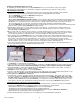
5. Tape the seams with duct tape or other water and tear resistant, utility-grade, poly-coated cloth backed tape that has a very
aggressive adhesive. (Photo 3). Tape over the lead wires running between the padding.
6. Avoid taping over WarmFlex’s heating wires.
7. The thermostat sensor wire should be routed up the wall to the thermostat electrical box. Place the tip of the sensor wire
evenly spaced between two WarmFlex heating wires extending about 6”-12” into WarmFlex. (Refer to Fig. 3 Sensor Wire
Location on page 5.) It is acceptable to use a utility knife to notch out a 1/4” x 1” piece of WarmFlex and the underlayment
to imbed the sensor (DO NOT CUT THE HEATING WIRE). You can tape the sensor wire in place but do not tape over the
sensor probe as this may cause heat build-up causing the thermostat to reduce power to WarmFlex heating elements.
1-D Floating Laminate or Wood Floor Covering Installation
1. When installing the floor, be careful not to damage WarmFlex’s heating elements. If the floor covering is not immediately
installed, protect WarmFlex with corrugated box material, carpet, luan plywood or similar material.
• Keep traffic to a minimum on installed WarmFlex prior to floor covering installation.
• Avoid dropping, rolling or dragging objects or tools over the heating elements.
• Be careful that nails, screws or other fasteners do not penetrate the floor in the area of WarmFlex. WarmFlex’s
heating elements can be damaged by fasteners penetrating the floor.
2. Install the floating laminate or floating wood floor according to the flooring manufacturer’s instructions.
Photo1
Photo 2
Photo 3
Underlayment padding
Photo1
WarmFlex