
Installation Guide

Rev.1.12.09.10 3
1. FLOATING HARD SURFACE FLOORS (including laminate, wood and interlocking tile)
1-A Electrical Rough-In
Install GFCI Breaker – (Over-current Protection)
1. WarmFlex™ must be installed with a ground fault circuit interrupter (GFCI) unless your WarmFlex model is equipped with
ground wire in which case only wet area installations (kitchen, bath) require GFCI. We recommend installing WarmFlex with
our programmable thermostat (purchased separately) with a built-in GFCI. If you are not using a thermostat with GFCI already
built-in, then install a dedicated, indicating-type GFCI. This GFCI serves as a local disconnect.
• Note: Follow all local building and electrical codes.
• It is possible to branch from an existing circuit if the Amps provided by the circuit are sufficient to supply the Amp load of
the floor heating mats and all other appliances that are or will be connected to the circuit. If the Amp supply is not
sufficient, install a dedicated circuit.
• Consult with a qualified electrician to determine if the circuit can handle the load and if the circuit is GFCI-protected. The
size of the breaker is determined by the total Amp load of the heated mats. You may need multiple breakers, multiple
thermostats or a contactor/relay for systems larger than 15 Amps.
Install Electrical Boxes
2. Thermostats are usually located near the power leads. However, they can be located almost anywhere, because the power
leads and the sensor wire can be routed to electrical junction boxes and extended to a location outside the heated room (such
as a utility room).
3. For the programmable thermostat, install a 1-gang (2” wide) or 2-gang (4” wide) electrical box with a 1-gang mud ring.
(Note: the 4” box provides more room to work with multiple lead wires). If using our manual thermostat, Model MTC, install a
2.25” wide or 4” electric box. Electrical boxes are typically located approximately 5’ from the floor for readability.
4. The floor sensor wire can be extended up to 50’ (maximum) if necessary.
Bottom Plate Work
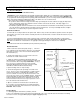
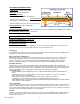
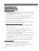
5. Drill or saw holes at the bottom plate (See Fig 1.) One hole
is for routing the power leads and the other hole is for routing the
thermostat sensor wire. These holes should be directly below
the electrical box(es).
6. Power lead conduit: remove one of the knock-outs in the
electrical box to install conduit for leads.
7. Install 1/2” minimum conduit from the bottom plate up to
the electrical box. Install 3/4” conduit if necessary to make room
for more lead wires when using multiple WarmFlexs. (See Fig 1.)
Close one end of conduit to junction box enclosure with
power supply
electrical box
for thermostat
electrical conduit
for lead wires
sensor
wire
Figure 1
appropriate fitting/locknut. Close bottom end of the conduit
flush with the wall and fit with insulated bushings
to prevent chafing of wire on exposed edge.
8. The thermostat (purchased separately) comes with a floor
sensor. The floor sensor can be installed in a conduit separate
from the power lead wire conduit although installation of the
sensor in conduit is not necessary. Check the resistance of the
sensor wire to be sure it is near 14.8 kOhms at 68° F. Suggestion:
install a 3/8” plastic or copper tube from the electric box going
down the wall and under the floor for sliding the sensor wire in
and out should it ever become necessary to replace the sensor.
Close the end of the tube under the floor.
9. Open a second knock-out in the bottom of the thermostat
box. Feed the sensor through the knock-out down through the
cut-out in the bottom plate, and out into the floor area where the
WarmFlex will be installed.
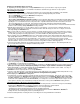
Rough-in Wiring
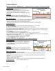
11. Install appropriate electrical wire (conductor) from the
WarmFlex
Floor Covering
power source and GFCI protection to the thermostat following all codes. Leave extra wire at the thermostat box for making
connections. Refer to the Typical Wiring Diagrams (Fig.4 on page 6) for help.
bottom plate
cut-outs
Lead wires
Install sensor probe evenly
spaced between heating wires