THERMOLEC Installation Instructions for Electric Boilers (CANADA) November 2011 VERSION 11
Installation Guidelines for Thermolec Electric Boilers Model B 1 Important 1.1 These instructions should be used as a general guide only. Electrical Code and local utility requirements must be followed and take precedence over these instructions. Thermolec electric boilers are manufactured with quality components for maximum life, durability and minimum service.
Components Mono or Dual energy controller Adjustable electronic aquastat (output temperature) Incoloy elements Manual reset thermal cut-out Solid state relays Thermostat terminals Electronic temperature sensor Fig. 2 Mounting holes Magnetic back-up contactor Outlet 1-1/4’’ NPT Boiler control transformer Temperature / pressure gauge 18” Circuit breaker (optional) supplied when required by N.E.C. Pump relay Inlet 1-1/4’’ NPT 9 1/2” Fig.
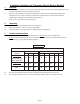
Table 2 Standard Model Specifications @ 240V / 1ph (Canada) Dual-Energy Models kW BTU / H Total Amps No. Of Power Supplies (Amps Per Breaker) B-5 B-6 B-8 B-9 B-10 B-12 B-15 5 6 8 9 10 11.5 15 17,060 20,472 27,296 30,708 34,120 39,238 51,180 20.83 25.00 33.33 37.50 41.67 47.92 62.50 1 x 30A 1 x 30A 1 x 50A 1 x 50A 1 x 60A 1 x 60A 1 x 80A Dual-Energy Models B-18 B-20 B-23 B-27 B-30 B-35 B-40 18 20 23 27 30 35 40 kW 61,416 68,240 78,476 92,124 102,360 119,420 136,480 BTU / H Total Amps 75.00 83.37 95.
Water circulation and plumbing notes 6.1 The system is designed to operate with a maximum output temperature of 180°F or lower and a temperature rise across the unit of 20°F or lower. Please refer to Table 4 for the recommended flow rate versus the capacity of the boiler. Table 4 Recommended Water Flow Rate vs Capacity Capacity (kW) Imp. Gallons / min US Gallons / min 3 0.9 1.1 5 1.5 2.0 6 1.7 2.0 8 2.3 2.8 9 2.6 3.1 10 2.9 3.5 11 3.2 3.9 12 3.5 4.2 15 4.4 5.3 18 5.2 6.2 20 5.8 7.0 23 6.7 8.0 25 7.
6.4 The automatic pressure relief valve supplied with the boiler is required to prevent dangerous pressure build-ups in the system in case of system malfunction and may under certain conditions vent hot water. Do not install the system where water could damage rugs, furniture, etc. When piping the relief valve to a drain, check with local authority for recommended method of installation. Do not open or tamper with the relief valve.
Electronic Aquastat MAXIMUM WATER TEMPERATURE MINIMUM WATER TEMPERATURE °C -10 °F +14 Fig. 4 8.7 -5 +23 0 +32 +5 +41 +10 +50 Fig. 5 The outdoor sensor will : a) Maintain the selected maximum water temperature when the outdoor temperature is at -10°C (+14° F) or colder. b) Automatically and proportionally compensate by varying the water temperature between the maximum and minimum when the outdoor temperature is between –10°C (+14°F) and +10°C (+50°F).
.8 9.9 9.10 9.11 9.12 9.13 9.14 Set the thermostat above the room temperature. The system should start. Make sure the pump starts running as soon as the system starts. Heating stages will be switched ON in sequence at 30 second intervals, confirmed by green lights on the left hand side of the PC board on the TH600 or by red lights on the right hand side on the D22-B. Wait for two minutes and measure the current drawn by the boiler and compare it with the one shown on the nameplate.
.3 10.4 10.5 10.6 10.7 Simulate a heating demand by setting the thermostat higher than the room temperature. Switch the mode selector to position and check that the burner responds to the thermostat demand. Switch the mode selector to the "Dual-Energy" position . Install a jumper between terminals "S1 / S2"; the electric mode is automatically selected. The pump will start and the heating stages will be switched ON in sequence at 5 second intervals.
3 CL 5 1 7 Torque Element Nuts at 130 inch-lbs Cylinder Output CL Torque Cover Bolts at 70 inch-lbs 14 8 2 6 Manometer 4 Fig. 8 Warranty Thermolec Ltd. warrants against defects in materials and workmanship the heat generator casing of its boiler and the heating elements for ten ( 10 ) years and all other components for two ( 2 ) years after date of shipment from its factory.
Electric Boiler Warranty Registration Form Name : _______________________________________________________________________________ Address : _____________________________________________________________________________ City : ________________________________________ Province / State : _______________ Postal / Zip Code : _________ Telephone : ___________________ Model No : ___________________ Serial No : _____________________ Installer Name : _________________________________________ Telephone : ______
Page 13 Cylinder Output C L 240/1 TMB 13” Cylinder 3000 3000 3000 3000 3.00 6.00 9.00 11.00 Front of cylinder Pressure\Temp. Guage 1 C L C L 8750 10000 8750 10000 Pressure\Temp. Guage 2 C L 1 5000 5000 8750 10000 Cylinder Output C L 3 Pressure\Temp. Guage Front of cylinder 2 C L CBLR055 CBLR055 CBLR058 CBLR059 1 Cylinder Output C L CBLR055 CBLR055 CBLR058 CBLR059 CBLR065 CBLR055 CBLR060 2 3 Pressure\Temp. Guage C L 4 1 Four Element Configuration 11.5 11.5 6.6 5.
Page 14 23" Cyl. 13" Cyl. 23" Cyl. 13" Cyl. 23" Cyl. Height 13" Cyl. 600/3 480/3 208/3 Volts / Phases 18.00 24.00 30.00 36.00 42.00 18.00 24.00 30.00 35.00 40.00 Total KW 18.00 24.00 30.00 36.00 347 277 208 Volt / element 3 3 3 3 3 3 3 3 3 3 # élém. 6 6 6 6 6000 8000 10000 12000 14000 6000 8000 10000 11600 13300 Watts 3000 4000 5000 5750 20.1 15.1 12.0 10.0 8.6 12.8 9.6 7.7 6.6 5.
EXPANSION TANK WATER FLOW DRAIN CONNECTION RE SS N DRAIN OR PURGE VALVE MAINTENANCE VALVE ELECTRIC BOILER SIO URE / PRES RE / T E M PÉ TU RA TEMPERATURE / PRESSURE GAUGE RE PRESSURE REDUCING VALVE SAFETY VALVE BLEEDING VALVE U AT WATER FEED AIR PURGER AUTOMATIC AIR VENT MAINTENANCE VALVE R SHUT-OFF VALVE MAINTENANCE VALVE CIRCULATING PUMP TEM PE SUPPLY TO RADIATORS RETURN FROM RADIATORS ROOM THERMOSTAT 120V / 1Ø PUMP POWER SUPPLY POWER SUPPLY LOAD MANAGEMENT CONTROL OUTDOOR RE
DRAIN OR PURGE VALVE MAINTENANCE VALVE N ROOM THERMOSTAT DUAL-ENERGY CONTROLLER BURNER PUMP CONTROL MAINTENANCE VALVE ELECTRIC BOILER SIO URE / PRES OIL / GAS BOILER P RETURN FROM RADIATORS EXPANSION TANK WATER FLOW DRAIN CONNECTION RE SS RE / T E M PÉ TU RA TEMPERATURE / SAFETY VALVE PRESSURE GAUGE BLEEDING VALVE RE PRESSURE REDUCING VALVE MAINTENANCE VALVE U AT WATER FEED AIR PURGER AUTOMATIC AIR VENT R SHUT-OFF VALVE MAINTENANCE VALVE CIRCULATING PUMP TEM PE SUPPLY TO RADI
RETURN FROM RADIATORS MOTORIZED VALVE A-C PORT NORMALLY CLOSED A-B PORT NORMALLY OPEN MV A B C MAINTENANCE VALVE DRAIN OR PURGE VALVE MAINTENANCE VALVE OIL / GAS BOILER MAINTENANCE VALVE BURNER PUMP CONTROL DRAIN CONNECTION RE SS N ROOM THERMOSTAT DUAL-ENERGY CONTROLLER ELECTRIC BOILER SIO URE / PRES RE / T E M PÉ TU RA TEMPERATURE / PRESSURE GAUGE SAFETY VALVE BLEEDING VALVE RE EXPANSION TANK MAINTENANCE VALVE U AT PRESSURE REDUCING VALVE AIR PURGER AUTOMATIC AIR VENT R WATE