
Instruction Manual


STEP 3 - (continued)
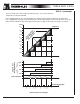
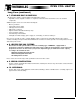
HYBRID CONTROL - Binary Mode
Binary staging f
or a 160 KW heater
.
SCR Step 1/16 10 KW
Step 1
1/16 10 KW
Step 2
2/16
20 KW
Step 3 4/16 40 KW
Step 4
8/16 80 KW
In this example, the control voltage 0-10 Volts DC is divided by 16 which gives an increment of
0.625
Volts per 10 KW step.
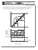
Here is how it works, in increments of 10 KW and .625 V input voltage:
Input voltage
KW output
Fixed steps on and SCR
from 0 to .625 V
0 to 10 KW The var
iable SCR step cov
ers the heat demand
from .625 to 1.25 V
10 to 20 KW step 1 + SCR (10 fix
ed + 10 SCR)
from 1.25 to 1.875 V
20 to 30 KW step 2 + SCR (20 fixed + 10 SCR)
from 1.875 to 2.5 V
30 to 40 KW step 1 + step 2 + SCR (30 fixed + 10 SCR)
from 2.5 to 3.125 V
40 to 50 KW step 3 + SCR (40 fixed + 10 SCR)
from 3.125 to 3.75 V
50 to 60 KW step 3 + step 1 + SCR (50 fixed + 10 SCR)
from 3.75 to 4.375 V 60 to 70 KW step 3 + step 2 + SCR (60 fixed + 10 SCR)
from 4.375 to 5 V
70 to 80 KW step 3 + step 2 + step 1+ SCR (70 fixed + 10 SCR)
from 5 to 5.625 V 80 to 90 KW step 4 + SCR (80 fixed + 10 SCR)
from 5.625 to 6.25 V 90 to 100 KW step 4 + step 1 + SCR (90 fixed + 10 SCR)
from 6.25 to 6.875 V
100 to 110 KW
step 4 + step 2 + SCR (100 fixed + 10 SCR)
from 6.875 to 7.5 V 110 to 120 KW step 4 + step 2 + step 1 + SCR (110 fixed + 10 SCR)
from 7.5 to 8.125 V 120 to 130 KW step 4 + step 3 + SCR (120 fixed + 10 SCR)
from 8.125 to 8.75 V
130 to 140 KW
step 4 + step 3 + step 1 + SCR (130 fixed + 10 SCR)
from 8.75 to 9.375 V 140 to 150 KW step 4 + step 3 + step 2 + SCR (140 fixed + 10 SCR)
from 9.375 to 10 V 150 to 160 KW step 4 + step 3 + step 2 + step 1 + SCR (150 fixed + 10 SCR)
Since the SCR step is kept small, it is cost effective compared to a full SCR 160 KW.
Hybrid Binary Load Diagram (Please see next page)
THREE
EASY
STEPS