THERMOLEC Certificate of Compliance Certificate Number: LR 30551-1 Revision: LR 30551-35 Issued to: THERMOLEC LTÉE/LTD 2060 Place Thimens St-Laurent, Québec H4R 1L1 The products listed below are eligible to bear the CSA Mark NOTE: The "NRTL/C" indicator also appears adjacent to the CSA Mark. Issued by: G. Raymond, Eng. Montréal, QC Canada Signature: PRODUCTS CLASS 2811 03 - HEATERS - Air - Stationary Type CLASS 2811 83 - HEATERS - Air - Stationary Type - CERTIFIED TO U.S.
THERMOLEC Certificate of Compliance Certificate Number: LR 30551-27 Revision: LR 30551-35 Issued to: THERMOLEC LTÉE/LTD 2060 Place Thimens St-Laurent, Québec H4R 1L1 The products listed below are eligible to bear the CSA Mark NOTE: The "NRTL/C" indicator also appears adjacent to the CSA Mark. Issued by: G. Raymond, Eng. Montréal, QC Canada Signature: PRODUCTS CLASS 2811 03 - HEATERS - Air - Stationary Type CLASS 2811 83 - HEATERS - Air - Stationary Type - CERTIFIED TO U.S.
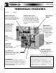
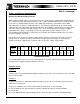
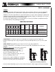
FEATURES THERMOLEC FEATURES Standard l Optional r MERCURY CONTACTORS r Used to power individual stages of heating. They allow a silent operation and are exceptionally reliable. DISCONNECT SWITCH r A built-in disconnect switch allows user to disconnect heaters individually in order to safely perform maintenance tasks. AUTOMATIC RESET CUT-OUT l The automatic reset thermal cut-out is a fail-safe, fixed temperature, disc type safety device that opens the circuit when it’s set point is reached.
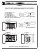
AVAILABLE MODELS MODELS SLIP-IN TYPE DUCT HEATERS AND FLANGED TYPE DUCT HEATERS SC Slip-in Open Coil (Fig. 1) ST Slip-in Tubular FC Flanged Open Coil FT Flanged Tubular (Fig. 2) RFC Round collar open coil (Fig. 3) Duct for Slip-in Heater RFT Round collar with Tubular elements Duct Flanged Heater Duct for for Flanged Heater Fig. 1 Fig. 2 Fig.
THREE EASY STEPS HOW TO SELECT AND SPECIFY IN THREE EASY STEPS Selecting the heater for your application can be done in three easy steps: 1- Determine heater capacity, voltage and electrical components 2- Determine duct dimensions, air requirements and mechanical options 3- Determine method of control, then select control components STEP 1 DETERMINE HEATER CAPACITY, VOLTAGE AND ELECTRICAL COMPONENTS Heater capacity Given CFM (volume of air in cubic feet per minute) and D ºT (temperature rise in º F ), th
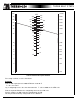
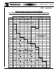
THREE EASY STEPS D T CFM 100 10.000 KW 80 60 130 50 90 250 200 150 175 110 120 30 55 35 25 45 50 30 32 20 15 20 10 7 5 100 6000 5000 80 70 40 8000 60 4000 40 27 3000 22 17 12 2000 9 6 4 10 1000 3 2 2 8 800 1.5 6 600 1.0 5 .75 4 .50 500 400 3 300 2 200 1 100 Abacus toChart determine the Kilowatts to determine theRequired required kilowatts For a rough estimate, use the chart above. Example: Find the KW required to raise 2000 CFM from -10 to 40 ºF.
THREE EASY STEPS STEP 1 - (continued) Power and Voltage Requirements Nominal and Standard Supply Voltages While a utility's voltage may be referred to by means of a nominal figure, actual applied voltage may vary over a fairly wide range depending on factors like the system's power distribution lines, and many others.
THREE EASY STEPS STEP 1 - (continued) 347 (277) V, Single Phase Power Supply When capacities are below 7 KW at 277 V and 8 KW at 347 V Thermolec recommends the use of the following arrangementsintoorder obtain the current most economical for heaters and electrical distribution. to keep imbalance to acost minimum. 600 V / 3 Ph or (480 V / 3 Ph) 4 wires POWER SUPPLY L1 L2 L3 N 347V (277) 347V (277) These voltages are generally derived from a 600 (480) volts - 3 phase 4 wire power supply.
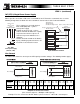
THREE EASY STEPS STEP 1 - (continued) Selection chart of most economical design for THERMOLEC modulating heaters KW/Voltage combination KW V 120 208 240 277 347 208 240 416 480 600 1 2 3 3 MOST ECONOMICAL 4 4.5 5 6 5.2 Selection of Economical Design 7 8 9 8.3 SECOND BEST CHOICE 10 11 12 9.6 11 13 14 15 13.8 14.4 16 16.6 18 20 22 LEAST ECONOMICAL 24 26 28 30 32 34 28.
THREE EASY STEPS STEP 1 - (continued) FUSING The National Canadian and Electrical Code requires that each power supply to a heater be individually protected by either fuses or circuit breakers external to the heater. Please see Pertinent Regulations. Additional sub-circuit fusing within the heater (built-in load fuses) may be either mandatory or optional and if optional, may or may not be recommendable.
THREE EASY STEPS STEP 1 - (continued) Contactors Contactors are used to power individual stages of heat or as back-up for safety switches. Contactors may be of two types: Partial line-break (or de-energizing) c c c c In the partial line-break arrangement the contactor opens the current path, thus de-energizing the heater. Full line-break (or disconnecting) The full line-break type contactor opens all ungrounded power lines in the heater. This may be ordered as an option (Request option C2).
THREE EASY STEPS STEP 2 DETERMINE DUCT DIMENSIONS, AIR REQUIREMENT AND MECHANICAL OPTIONS Air Flow requirements and Minimum Velocity When there is a choice in heater face dimensions the specification writer has several good reasons for favoring the smaller rather than the larger heater face area: The smaller sized, higher velocity electric coil will perform better, weigh less and cost less per KW than an otherwise identical larger coil.
THREE EASY STEPS STEP 2 - (continued) Please refer to the table on page 16 for tubular elements. Example: Find the minimum air flow requirement for a 65 KW 1 stage heater in a 24” wide by 18” high duct. 24” x 18” = 3 square feet 144 A Calculate duct area in square feet. B Calculate KW per square foot per stage. C Using the Air flow requirement curve above, find 21.66 on the vertical scale. Read the minimum velocity required on the horizontal axis, which is approx. 1150 FPM.
THREE EASY STEPS STEP 2 - (continued) Airflow Uniformity In order to prevent hot spots, the air flow must be uniformly distributed across the heater area. The following figures illustrate typical heater mis-application where the airflow is not uniform. An NEC article (please see below *) specifies that a heater should not be installed closer than 4 feet downstream or 2 feet upstream from a fan outlet, an abrupt transition, an elbow or any other kind of obstruction in the duct.
THREE EASY STEPS STEP 2 - (continued) OPEN COIL vs TUBULAR elements THERMOLEC manufactures both open coil and tubular duct heaters. It is widely acknowledged that tubular elements find practical application under certain circumstances (service conditions include possible contact by personnel, presence of dust or particles in the air flows or atmospheric conditions).
THREE EASY STEPS STEP 2 - (continued) Exclusive Design advantage of the Thermolec Tubular heater construction Thermolec Tubular elements can be removed through the control box, which avoids the need to remove the heater from the duct and thus reduces maintenance costs. However, precautions must be taken in terms of clearance when installing the heater in order to take advantage of this feature. Please refer to SECTION 2 of this catalog for more detailed considerations about open coil and tubular elements.
THREE EASY STEPS STEP 2 - (continued) Size Limitations Although there are practically no limitations to the maximum size of Thermolec custom-built heaters, all CSA listed heaters must comply to the following minimum dimensions: Slip-in Type Open Coil Flanged Type Open Coil Slip-in Type Tubular Flanged Type Tubular Minimum Duct Width Dimension “W” 6” 5” 8” 7” Minimum Duct Height Dimension “H” 5” 4” 6” 6” Size Limitation Table CSA listed custom heaters are available in virtually any KW rating.
THREE EASY STEPS STEP 2 - (continued) Variable Air Volume units (VAV) The "Thermo-V" electric heater developed by Thermolec eliminates the common problems that are encountered in the application of an electric heater to a VAV box as described below: A. When the VAV Box is in the minimum opening position, the air flow is often below the minimum required to operate a standard electric heater, causing element overheating and possible tripping of the thermal cut-outs.
THREE E A S Y STEPS STEP 2 - (continued) Thermolec has developed and patented an innovative solution to eliminate these problems: The Proportional Electronic Air Flow Sensor. The Air Flow Sensor responds to the radiant heat of the heating element which, in turn, is influenced by the air flowing through the heater to dissipate the heat. The patented sensor and associated electronic controller modulate the power to the heater, adjusting the heater’s capacity to accurately match the air flow available.
THREE EASY STEPS STEP 2 - (continued) Universal mounting of Thermolec heaters Unique feature By design, all Thermolec heaters are made non-sensitive to air flow direction. The built-in high limit thermal cut-outs are located in such a way that the air flow could be in any direction without impairing safety and the same heater could be installed in a horizontal or vertical duct. Multiple Heaters in a duct Normally, electric heaters are not designed to be used in series in a heating installation.
THREE EASY STEPS Heater Installation Installation of Slip-in heater Installation of Slip-in heater STEP 2 - (continued) Installation of flanged heater Details of the Thermolec Mechanical construction Detailed dimensions: Model SC Dimensions Model FC Dimensions Conversion to metric 1” = 25.4 mm 3/4” = 19.
THREE EASY STEPS STEP 2 - (continued) Protective screens Screens on both sides of the heater prevent any accidental contact by personnel or tools with electrically de-energized but still "live" coil elements. Heater with screens Bottom control box In special conditions, where there is not enough space to ensure proper installation and maintenance, Thermolec can supply a bottom control box designed to maintain the horizontal orientation of open coil elements.
THREE EASY STEPS STEP 2 - (continued) Nema 4 or Weatherproof control Box In locations subject to frequent washdowns (i.e. mines, food processing plants), the electric heaters must be supplied with a NEMA 4 control box. The terminal box is all welded, painted steel, with a hinged, gasketed cover and hold-down clamps. When required, the terminal box could be made in stainless steel (specify Nema 4X). The electrical contractor must install water-tight connectors for power supply and control wires.
THREE EASY STEPS STEP 2 - (continued) Special Heaters Thermolec manufactures heaters with special specifications to meet the needs of any OEM manufacturer. COLD SECTION HEATING SECTION COLD SECTION Special Heater with no-heat sections Process Heaters Thermolec manufactures process heaters for drying, curing, baking, etc...
THREE EASY STEPS DETERMINE METHOD OF CONTROL AND SELECT CONTROL STEP 3 - COMPONENTS Temperature Control Modes and Staging In selecting temperature controls the specification writer will generally wish to consider both control accuracy and cost. To provide an acceptably close match of heater output to the system's varying demand for heat it is usually necessary to divide the total KW capacity into separately controlled increments or "control stages".
THREE EASY STEPS STEP 3 - (continued) ON - OFF Control Mode Air temperature is controlled by switching on and off selected control stages of the heater or, on single stage heaters, the entire heater. The ON / OFF mode is practical up to two control stages. It is recommended for most COARSE control accuracy applications and is satisfactory up to a maximum of 25 ˚F D T temperature rise per stage.
THREE EASY STEPS STEP 3 - (continued) Pulse Width Modulation Diagram In the above example: 10% 50% 80% 100% = = = = 12 cycles ON, 108 cycles OFF 60 cycles ON, 60 cycles OFF 96 cycles ON, 24 cycles OFF 120 cycles ON 0.2 seconds of heating on 2 seconds 1 second of heating on 2 seconds 1.
THREE EASY STEPS STEP 3 - (continued) Comparison between ON/OFF and proportional control Due to it’s high differential, ON/OFF control mode wastes a lot of energy. The graphic below shows how the ON/OFF method creates high "overshoot" above the temperature set point while the electronic proportional method keeps the temperature close to the set point. The shaded areas correspond to wasted energy.
THREE EASY STEPS STEP 3 - (continued) Thermolec strongly recommends the use of SCR proportioning controls for the best results in energy efficiency and maximum comfort. When the output of the entire heater is being modulated in this manner, the control system is defined as "FULL SCR". When one control stage only is controlled by a SCR while the balance of the heater stages are handled by ON - OFF control, the system is defined as "HYBRID or VERNIER".
THREE EASY STEPS STEP 3 - (continued) HYBRID or VERNIER CONTROL - Principles Where FINE control accuracy is required and the heater capacity is too high to be handled economically by "FULL SCR", (80 Amps max.), Thermolec recommends a combination of a smaller SCR and a step controller, both being controlled by the same input signal. In this system, the "SCR" is the modulating heating stage. The other heating stages are controlled by the Thermolec electronic step controller. D46 (the Sequential mode).
THREE EASY STEPS STEP 3 - (continued) Since the SCR step is kept relatively small (53.3 Kw ), it is still cost effective compared to a full SCR 160 KW. In the following graphic, the sequential loads are switched ON and OFF to match the heat demand. Lay a straightedge vertically at any position of the control input voltage and find exactly which stages are ON or OFF. The SCR not only fill the gaps but overlaps the gaps between the fixed steps at all times.
THREE EASY STEPS STEP 3 - (continued) HYBRID CONTROL - Binary Mode Binary staging for a 160 KW heater. SCR Step 1/16 10 KW Step 1 1/16 10 KW Step 2 2/16 20 KW Step 3 4/16 40 KW Step 4 8/16 80 KW In this example, the control voltage 0-10 Volts DC is divided by 16 which gives an increment of 0.625 Volts per 10 KW step. Here is how it works, in increments of 10 KW and .625 V input voltage: Input voltage KW output Fixed steps on and SCR from 0 to .
THREE EASY STEPS STEP 3 - (continued) In the following graphic, the binary loads are switched ON and OFF to match the heat demand. Lay a straightedge vertically at any position of the control input voltage and find exactly which stages are ON or OFF. The SCR modulating step fills the gap between the fixed steps at all times.
THREE EASY STEPS STEP 3 - (continued) Summary of Temperature Control 1- Electric ON / OFF thermostats are available up to three stages for room or duct control and up to four stages for duct control only. Three and four stage thermostats are not recommended for FINE or MEDIUM temperature control because of their large differentials. However, they are suitable for COARSE control. 2- P.E.
THREE EASY STEPS STEP 3 - (continued) Modulating Room Thermostats RT The Thermolec RT electronic modulating room thermostat is a thermistor proportional type that is compatible with all Thermolec electronic controls. ABS casing. Thermistor based, proportional control, two wire type, with built-in adjustable set point. Standard range: 10 to 30 ˚C, (50 to 86 ˚F).
THREE EASY STEPS STEP 3 - (continued) Modulating Duct Thermostats DT The Thermolec DT electronic modulating duct thermostat is a thermistor proportional type that is compatible with all Thermolec electronic controls. ABS casing for temperatures up to 65 ˚C. Metal casing for temperatures over 65 ˚C, two wire type, with built-in adjustable set point. DT - ABS Casing Model # DT-1815 DT-037 DT-1040 DT-3265 DT-6590 DT-80155 Range ˚C ˚F.
THREE EASY STEPS STEP 3 - (continued) SCR Controller The SCR is a time proportioning type controller that modulates the heater and supplies the exact amount of power to match the heat demand. Input: Output: Thermistor thermostat (RT or DT), 0 - 10 VDC, 4 - 20 mA, 0 - 135 Ohms. Single or three phases load, 20, 30, 40 and 80 Amps @ 600 V.
THREE EASY STEPS Warranty 1- Thermolec Ltd. guarantees their heater resistance elements and other built-in components against any defect in workmanship and material for a period of one year, effective date of shipment from it’s factory. Any claim under this guarantee will be considered only if the product has been installed and operated in accordance with Thermolec’s instructions.
THERMOLEC OPEN COIL HEATER SPECIFICATION FOR OPEN COIL HEATERS Long Form Supply where indicated in these specifications, or where shown on drawings, CSA (NRTL/C) approved open coil duct heaters as manufactured by THERMOLEC. ☛ 1- CONSTRUCTION: • Frame shall be corrosion-resistant and made of galvanized steel of suitable gauge as required by CSA. • Coils shall be made of high grade Nickel-Chrome alloy and shall be insulated by floating ceramic bushings from the galvanized steel frame.
THERMOLEC OPEN COIL HEATER Long Form (continued) ☛ 7- STANDARD BUILT-IN CONTROLS: All duct heaters shall be complete with the following built-in controls: • High limit cut-outs, magnetic contactors as required, control transformer and air flow sensor as standard components.
THERMOLEC OPEN COIL HEATER Short Form • Supply where indicated in these specifications CSA (NRTL/C when required) approved duct heaters as manufactured by THERMOLEC. • Coils shall be of High Grade Nickel-Chrome alloy and shall be insulated by floating ceramic bushings from the galvanized steel frame. Coil terminal pins shall be stainless steel insulated by means of non-rotating ceramic bushings. • Heaters shall be model SC slip-in type, as shown on the plans or on the heater schedule.
THERMOLEC SPECIFICATION TUBULAR HEATER SPECIFICATION FOR TUBULAR HEATERS Long Form Supply where indicated in these specifications CSA (NRTL/C) approved tubular duct heaters as manufactured by THERMOLEC. ☛ 1- CONSTRUCTION: • Frame shall be corrosion-resistant and made of galvanized steel of suitable gauge as required by CSA. • Heating elements shall be tubular type made of heavy gauge Incoloy 800 filled with compacted magnesium oxide insulating powder.
THERMOLEC TUBULAR HEATER SPECIFICATION Long Form (continued) ☛ 6- INTERNAL WIRING: • All internal wiring shall terminate on clearly identified terminal blocks. • A wiring diagram shall be installed on the control box cover. • Prior to shipping, heaters shall withstand tests as required by CSA.
THERMOLEC TUBULAR HEATER SPECIFICATION SPECIFICATION FOR TUBULAR HEATERS Short Form • Supply where indicated in these specifications CSA (NRTL/C when required) approved duct heaters as manufactured by THERMOLEC. • Heating elements shall be tubular type made of heavy gauge Incoloy 800 filled with compacted magnesium oxide insulating powder. Above 277 Volts or 30KW, each tube shall be of "U" type and shall be removable through the control box without removing the heater from its ductwork.
THERMOLEC THERMO-V SPECIFICATION THERMO-V SPECIFICATION Supply where indicated in these specifications, or where shown on drawings, CSA (NRTL/C) approved THERMO-V type heaters specially designed for VAV boxes and manufactured by THERMOLEC.
THERMOLEC Application Notes OPEN COIL AND TUBULAR ELEMENTS CONSIDERATIONS 2060 Lucien Thimens Street St-Laurent, Quebec H4R 1L1 Tel.
THERMOLEC APPLICATION NOTES Open coil and tubular elements considerations THERMOLEC manufactures both open coil and tubular duct heaters. It is widely acknowledged that tubular elements find practical application under certain circumstances (service conditions include possible contact by personnel, presence of dust or particles in the air flow or atmospheric conditions).
THERMOLEC APPLICATION NOTES 4-KILOWATTS PER SQUARE FOOT Since tubular elements surface temperature lag behind the resistance wire temperature due to mass and insulation, and in order not to exceed the maximum temperatures allowed by UL, a tubular duct heater is not permitted to have the same concentration of wattage as an open coil heater. Thermolec open coil duct heaters have listing of 22.5 KW per square foot. For tubular duct heaters, the limitation is usually about 13KW per square foot.
THERMOLEC APPLICATION NOTES 6-WEIGHT Open coil duct heaters weigh considerably less than comparable tubular heaters, hence they offer additional cost savings in packing, shipping, installation and installation hardware. 7-WIRE SURFACE TEMPERATURE A well-designed open coil element operates "in the black", at a temperature range of 750ºF to 900ºF.
THERMOLEC ENGINEERING AND APPLICATION GUIDE Selection guide for heating elements Following are a few factors commonly used to determine the choice of construction. FACTOR OPEN COIL TUBULAR COIL TEMPERATURES Resistance coil, exposed directly to airstream, runs cooler than coils imbedded in sheathed elements. Tubes run hotter than open coil or finned tubular. Temperatures are kept within safe limits by reducing watt densities.
THERMOLEC
THERMOLEC Title / Titre Drawing number / Numéro de dessin MST0
THERMOLEC Title / Titre Drawing number Numero de dessin MFC0 - 10LS - 0002 - 000K
THERMOLEC Title / Titre Drawing number / Numéro de dessin MSC0 - 10LS - 0002 - 000M
THERMOLEC Title / Titre Drawing number / Numéro de dessin MRFC - 40LS - 0002 - 000G
2060, LUCIEN-THIMENS STREET, MONTREAL, QUEBEC, CANADA, H4R 1L1 TEL. : 1-800-336-9130 FAX : 1-800-336-3270 WEB : thermolec.
FRESH AIR HEATER FRESH AIR HEATER Application # 1 Thermo-Air complementing a heat recovery ventilation system. At low temperature, a heat recovery ventilation system cannot recover enough heat to pre-heat the incoming outside air to a comfortable level. A THERMO-AIR heater is the ideal solution to restore efficiency to the system. It is equipped with an electronic controller that proportionally modulates the heating load to match the exact capacity required, thus minimizing operating cost.
FRESH AIR HEATER FRESH AIR HEATER Application # 3 Fresh Air make-up. A THERMO-AIR heater combined with a small fan is all that it takes to create a low-cost, efficient and accurate air make-up. This new heater is equipped with a modulating controller which uses the minimum amount of energy, thus avoiding waste, and a super-sensitive air flow sensor which permits the heater to operate only when the fan is running.
ZONE HEATER ZONE HEATER Application # 1 Central ventilation with zone heaters. In this application, there is no furnace required but only a central blower that provides continuous ventilation. The heating of the forced air is done in each zone, controlled by an accurate electronic thermostat supplied with each heater. Each thermostat controls it’s heater in a proportional way, thus avoiding a waste of energy and providing maximum comfort.
ZONE HEATER Application # 3 Stand alone heating system. A THERMO-ZONE heater combined with a small ventilation unit and two grilles or diffusers is all that it takes to create a small, accurate and low-cost heating system. This new heater is equipped with a modulating controller which uses the minimum amount of energy, thus avoiding waste, and a supersensitive air flow sensor which permits the heater to operate only when the fan is running.
THERMO-AIR & THERMO-ZONE How to evaluate your heating requirement? Considering today’s insulation standards, an easy to remember rule of thumb is that the heating capacity should be equal to 8 watts per square foot. A 1 KW heater would then be sufficient to heat a surface of 1000 ÷ 8 = 125 square feet. Adding a safety factor would bring the surface to approximately 120 square feet, i.e. a 12’ x 10’ room. We suggest: Up to 120 sq. ft. from 121 sq. ft. to 240 sq. ft. from 241 sq. ft. to 360 sq. ft.
THERMO-AIR & THERMO-ZONE Specifications and Safety Features Heating capacity of 1 to 8 KW. Standard voltages 120, 208, 240, 277 and 347. Standard round collar dimension 6" and 8" for easy installation between the floor joists (or basement false ceiling). Other dimensions up to 12" diam. and 24"x18" duct also available. Please contact factory. The unit operates at low temperature (60ºC / 140ºF max.) and has three levels of protection: • one automatic reset cut-out calibrated at (51.
THERMO-AIR & THERMO-ZONE Graphic for proportional control Proportional Control Diagram - Principle of the Pulse With Modulation By comparing the input signal with an internally generated reference signal (triangle wave), the controller activates the SCR output in a range of 0 to 100%. On this graphic, every time the horizontal line corresponding to the input (in this example, 10 %, 50 % and 80 %), crosses the reference signal, the heating elements are switched ON or OFF.
SONDE DE DEBIT D'AIR AIR FLOW SENSOR SONDE DE DE GAINE DUCT SENSOR D22-TF THERMOLEC
SONDE DE DEBIT D'AIR AIR FLOW SENSOR SONDE DE DE GAINE DUCT SENSOR D22-TF THERMOLEC
Specification sheet NRTL/C Box Type Open Type Description Solid State Relays are designed for controlling large amounts of power with a Logic Input Signal. The internal circuit features a dual SCR design for full wave capability and a Zero Crossing Detector. An opto-coupler isolates the input signal from the power circuit.
TransAX™: A superior protection ! Usually there are two methods used to absorb transients: RC networks and Metal Oxyde Varistors (MOV). Both methods are unsufficient in certain cases. The new TransAX™ option eliminates the problems normally associated with RC networks and MOV’s. It is an active component that can quickly switch very high currents. Instead of absorbing excessive energy endlessly, at a predetermined programmable trip point it passes the energy back to the line.
Specification sheet RT - Room thermostat (proportional) • 2 wires • Low voltage • Adjustable set point • Thermistor sensor • White ABS housing • Adjustment Range: 10 - 30° C (50 - 86° F) • Special ranges available upon request THERMOLEC Electric Heating and Controls TEL: 514-336-9130 FAX: 514-336-3270 2060, Rue Lucien-Thimens, Montréal Québec, Canada, H4R 1L1 RT-1030
Specification sheet 3" Sensing device MIN X MA (Thermistor) 3" 1.
Specification sheet Sensing device (Thermistor) 6" 3" X MA 3" DS MIN 3" 3" 1.25" RA 1.