
User Manual


Page 24
CONTRACTOR
18. Making Electrical Connections
NOTE : All internal wiring is done at the factory. All external wiring shall be done by a qualifi ed electrician and
must conform to procedures, regulations and local codes.
18.1 A dedicated breaker in the main panel (or fused disconnect) must be installed.
18.2 Ensure that the wire size and protection equipment conform to the sizes required by the Electrical
Code.
18.3 Wire according to the wiring diagram supplied in the cover of the unit.
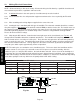
18.4 Starting the fan is mandatory with this type of humidifi er. The electronic controller board has a control
relay that supplies a dry contact at the terminals marked “FAN” to start the furnace fan. The installer must use
this contact to engage a relay that starts the furnace fan motor. Please refer to the furnace instruction manual
to fi nd the right wiring diagram. The standard rating of these contacts is 3A @ 240VAC or 6A @ 120VAC.
Please do not exceed these ratings.
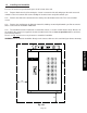
18.5 Adjusting the DIP switches, located on the lower right corner of the circuit board (see Fig 18a), will
change how the humidifi er determines automatic tank fl ushes. The humidifi er will completely drain and refi ll
with fresh water after a set number of “refi ll cycles”. Every time the unit replenishes the tank while producing
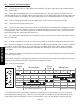
steam is counted as one cycle. The table below shows how to set the DIP switches in order to make the unit
fl ush the tank at different intervals. To keep deposits in the tank to a minimum, by default the tank will fl ush
every 30 cycles which equals approximately 5 hours of operation.
NOTE: The total cycles are cumulative across humidistat cycles. This means that if the humidistat satisfi es
when the counter is at 15 cycles, the count will resume from 15 upon a new call for humidity. After the
number of cycles, as set by the DIP switches, the tank will drain and refi ll. If there is no call for humidity for 7
consecutive days, the tank will be drained and wait for future demand from the humidistat. Cycle selection for
the DIP switch settings should be based on water hardness conditions as stated in the chart below. Depending
on the water quality the unit may drain more frequently that the DIP switch setting.
Switch numbers on DIP-switch
1 2 3 Cycles Before Tank Flush Water Hardness
OFF OFF OFF 180 Soft 0 - 60 mg/L
ON OFF OFF 120 Moderate 60 - 120 mg/L
OFF ON OFF 60 Hard 120 - 180 mg/L
OFF OFF ON 30 (DEFAULT) Very Hard > 180 mg/L
Fig 18a
FAN
GIN24V
A
H-STAT
A A
Fan
Relay
Fill LED
Drain LED
&+2UYKVEJ
ON
1 2 3
OFF
ON