
Operating Instructions and Installation Instructions


Page.23
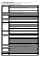
11. PLACING THE UNIT (first read “General instructions”)
Please note: Before placing the unit, we recommend you first read Chapter 7 “Concentric flue system” on
page 11.
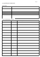
11.1 Unit components (see page 34, figures 6 and 7.)
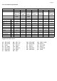
1 Unit 5 Window 9 Set screw 13 Baffle plate
2 Stainless steel front 6 Burner plate 10 Adjustment leg 14 Restriction plate
3 Glass strip 7 Burner 11 Wall brackets
4 Glass strip fixing bolts 8 Bottom plate 12 Control box
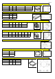
11.2 Connection to the gas pipes (see also page 25 for details)
You can determine where the gas pipes will be placed, dependent on the layout. Ensure control equipment is not
twisted during installation and there is no excessive tension. Accessibility of various connection points in relation
to components need to be maintained. After installation, check the connections for tightness in relation to gas.
Use a 1/2“ gas tap with connection. Ensure the gas pipes are dirt-free and sand-free, and gas and combustion
products from various parts and functioning is correct. The gas connection should only be undertaken when the
electricity supply is dead. This prevents any damage occurring to the gas control equipment.
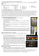
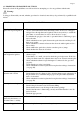
11.3 Preparation and installation of the unit
* Remove the packaging and check the unit for possible damage.
* Note: place the unit on a stable surface.
* Do not place the unit on its back or on its side.
* Take the lifting frame (A) out of the packaging and use it to place the unit (B) at its
intended location
* The window should now be removed in order to take the additional parts out of the
unit.
* Remove the glass strip (C) by unscrewing the 3, 4 or 5 countersunk Allen screws
(page 34 figure 6-4).
Carefully remove the glass strip from its fixture, possibly with the aid of a screw
driver.
* By placing the supplied suction cups (D) evenly over the glass window, the window
can be easily removed from the unit by first carefully moving it upwards and then
very carefully and slowly pulling the bottom of the window towards you; next, put the
window down and leave it in a safe place where it cannot be broken or damaged.
Please note: the window is very fragile.
You should therefore be very careful when moving/ installing the window!
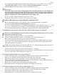
* Next, take the packaged components out of the unit and check to make
sure they are not damaged or broken.
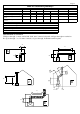
* Situate the unit (see page 35 figures 8 and 9as an example of an instal-
lation location) in your chosen installation location using the lifting
frame (A and B). At the rear and the sides, the unit must have at least
50 mm clearance from fireproof built-in materials. Install the convec-
tion set and position the supplied convection grilles at least 50 cm be
low the ceiling (see page 35 and 36 figures 8C and 9C) on the appropri
ate wall. A lowered ceiling inside the whole structure (fireproof built-in
materials) could be a possible solution in the event of a situation with a
visual obstruction.
Please note: Convection temperature output can be over 100 °C at
the convection grilles
Attention: in an installation location similar to figure 7, a mantle iron will have to be installed. See also the
detail on page 35figure 8A for the installation of the mantle iron.
* The legs of the unit can provide additional height of up to 300 mm (min. 185 and max. 485) for the rough
adjustment using the set screw (9). The adjustment legs (5) allow the unit to be adjusted more finely.
* Attach the unit to the wall using the wall brackets (11) for a stable installation.
A
B
1
D
C