
Operating Instructions and Installation Instructions


Page.16
Do not extend the thermocouple supplied to the pilot set
Extending the thermocouple beyond its limit will lead to a reduction in voltage. This may, in turn, lead to the
magnetic coil not being activated.
Prevent leakage of the ignition spark to parts of the installation other than the ignition rod at the pilot.
Ensure the ignition cable is not in contact with the shell or other metal parts. If a cable extension is used, ensure
that connections are additionally insulated using silicone.
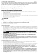
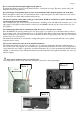
The receiver and the control units on the gas control block should be switched on to ensure automatic start
-up through the manual transmitter.
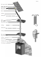
The oval disk on the gas control block should be turned to the ON position. The I/0 switch should be set to 1. See
photograph 2. The ignition cable should be connected to the SPARK connection point on the receiver box. See
photograph 1.
The manual transmitter has to communicate with the receiver. This has to be ‘learnt’.
Press the RESET button using a blunt object. (See photograph 3.) Continue to press this button until you hear a
short beeping sound, followed immediately by a long beeping signal. Release the button. Direct the manual trans-
mitter towards the receiver and press the arrow down until you hear a long beeping sound. The gas control button
will now move for a short period.
The manual transmitter has now learned the setting with regard to the receiver and the unit can now be ignited
using the remote control.
The system’s thermostat sensor is in the manual transmitter.
The manual transmitter operates best at a distance of 2 or 3 metres from the unit. Although communication oc-
curs via short wave radio signals, it is recommended to place the hand transmitter in view of the gas apparatus in
a place where the user wishes to experience a pleasant temperature. Do not place the manual transmitter in direct
sunlight or other warm location. The thermostat measures the temperature and regulates the flame size of the gas
unit accordingly.
Only remove batteries using non-metallic tools.
Removing batteries with a metal object may damage the electronic control permanently.
Photo 2
Photo 3
Photo 1
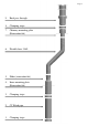
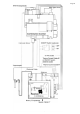
40 mm