Page.
TABLE OF CONTENTS 1 . General Page.2 Page 3 2. Safety device 2.1 Safety Page 4 3. Remote control 3.1 General 3.2 Manual transmitter 3.3 Screen setup 3.4 Time setup 3.5 Setting the Timer 3.6 Operation (remote control) 3.7 Possible error messages 3.8 Setting the flame height / extinguishing the flame 3.9 Switching the unit off 3.10 Inserting and replacing the batteries Page 5 4. Manual control 4.1 Igniting the fire 4.2 Extinguishing the fire 4.3 Switching the unit off Page 8 5. Initial start-up 5.
Page.3 We hope you really enjoy the warmth of your new gas fire. Read these instructions carefully before installing and using the gas fire. Keep these instructions in a safe place. Always provide the following information if the gas fire breaks down: model and serial number, which can be found on the unit. Your purchase invoice is your proof of warranty. 1. General The entire unit is delivered to you with your choice of mantle and/or accessories.
Page.4 2. SAFETY DEVICE The unit is fully safeguarded by means of thermo-electric pilot light protection to prevent unforeseen discharge of gas from the main burner. 2.1 Safety Do not place ceramic burner decoration material or logs against the pilot burner. Ensure the pilot light is able to burn freely over the main burner. Good ignition of the main burner is only guaranteed if this is the case. Not adhering to these instructions can lead to dangerous situations.
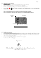
3. REMOTE CONTROL 3.1 General * The unit is operated using a radio-controlled remote control. This consists of a manual transmitter and a receiver. The receiver is connected to the gas control block. The receiver and the gas control block are located in the operating box. If there is no change in flame height for a 6-houre period the transmission / communication turn down application wil turn down the pilot flame.
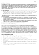
Page.6 3.6 * * * Operation (Remote Control) Igniting the flame Open the gas shut-off cock that has been installed in the gas pipe to the unit. Press the “O I” switch on the gas control block to the “I” position. Turn the operating button on the gas control block into the ON position. * Press the OFF and (large) switches on the remote control at the same time. A short sound signal will confirm commencement. Short sound signals will then follow until the pilot light and main burner are ignited.
3.8 Setting the flame height / extinguishing the flame * After the burner is ignited, the flame size will adjust to its maximum height automatically. * Press the button Page.7 (small) on the image of the flame to reduce the height and to switch the burner off. (Extinguishing the flame: “STAND BY”). (Press the key for a short time to gradually reduce the flame.) * Press the (large) button to increase the flame height. (Press the button briefly to gradually increase the flame height) 3.
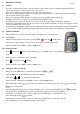
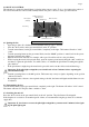
Page.8 4.0 MANUAL CONTROL The unit may be operated by hand if there is a defect in the remote control. To do so, the ignite (piezo)cable of the receiver must first be removed and carefully slid into the piezo connector on the gas control block. Small metal circle for Manual ignition Piëzo Ignitter (Manual) Main valve knob Manual knob Piëzo Knop “O I” Switch Microswitch 8 Wire Receiver Jack (Combination Control, Cover Manual position 4.
Page.9 5. INITIAL START-UP The unit has a layer of heat-resistant varnish that resists very high temperatures. An unpleasant smell may develop in the first hours after starting the unit due to burning in of the varnish; however, this is not dangerous. To accelerate this process, allow the unit to burn at the highest setting for several hours and ventilate the area well. After the first time the unit is turned on, a light deposit may form on the inside of the window. This is due to the varnish hardening.
Page.10 6. INSTALLATION INSTRUCTIONS Important The installation may only be performed by an authorised person 6.1 General instructions * The gas fireplace must be installed, connected and inspected as a closed unit by a qualified fitter, according to national, regional, and local standards and regulations. * The flue tube system and the outlets in the outer wall or roof face must also meet the requirements outlined in the applicable standards and regulations.
7. CONCENTRIC FLUE SYSTEM CC Page.11 The concentric flue system consists of a 100mm or 130mm Ø inner flue concentric with a 150 mm or 200 mm Ø outer flue. These flues have been set up concentrically; the combustion gases are exhausted through the internal flue while the fresh combustion air is supplied between the internal and external flues. 7.1 Components of the concentric flue system. (See page 29,30 and 31) Different connections are possible using the concentric flue system.
Page 12 Page.
7.3 Installation instructions regarding existing flues. Page.13 Instructions The flue gas exhaust system falls within category C91 and must be built in accordance with national rules and regulations and the instructions of the manufacturer, as specified in the documentation and installation instructions. This means, among other things, that the chimney pass-through must not be smaller than 150 mm round / square, but no larger than 200 mm, and not ventilated by grilles etc.
Page.14 9. Roof pass-through 8. Clamping strips 7. Chimney mounting plate (Renovation kit) 6. Flexible hose 316L 5. Slider (renovation kit) 4. Inner mounting plate (Renovation kit) 3. Clamping strips 2. CC Fitted pipe 1.
Page.15 8. Instructions for the Mertik Maxitrol GV60 and the Remote Control: Ensure that the fuel supplied to the unit is clean and free from particles and moisture. Before a gas supply pipe (new or existing) is connected to the main gas pipe at the gas meter and to the gas control block of the unit, clean and dry compressed air should been blown through it. Cut copper pipes as well as aluminium pilot pipes must be deburred and blown clean before they are connected.
Page.16 Do not extend the thermocouple supplied to the pilot set Extending the thermocouple beyond its limit will lead to a reduction in voltage. This may, in turn, lead to the magnetic coil not being activated. Prevent leakage of the ignition spark to parts of the installation other than the ignition rod at the pilot. Ensure the ignition cable is not in contact with the shell or other metal parts. If a cable extension is used, ensure that connections are additionally insulated using silicone.
Page.17 8.1 Mertik GV60 Troubleshooting Flow Chart No ACTION 1. Option: wall switch START: press ON button > wall switch works. 1. Manual transmitter START: press both buttons to start ignition sequence. Beep will occur each second Possible problem/cause Solution NO Bent pin on switch, or cable not operating properly. Straighten pin, replace wall switch or cable. NO Manual transmitter battery low. Replace battery, 9V quality alkaline! Receiver batteries low. Replace batteries, 1.
Page.18 No ACTION 3. NO Possible problem/cause Solution Ignition components not operating properly. Check connection between cable & IGN electrode. Check IGN electrode spark gap. Check IGN electrode for discharge to ground (break in ceramic). Check IGN cable for damage Increase distance between IGN cable and all metal parts. Check that spark does not discharge to ground at location of spark plug connection. Shorten cable if possible. If applicable, provide extra insulation with silicon hose etc.
Page.19 No ACTION 6. Possible problem/cause Solution NO Resistance in thermo current circuit too high. Check cables and connections in thermo current circuit. Magnet unit drops (audible click) Not enough heat on thermocouple. Check position of pilot to thermocouple and intensity of pilot flame. Low voltage from thermocouple. Check connections and, if necessary, replace thermocouple. Do not overtighten the connections! Short because thermocouple end is damaged.
Page.
Page.21 9.
10. Maintenance activities. . Page.22 Please note: turn off the gas supply and power supply as much as possible during maintenance activities. Maintenance activities should be performed by a qualified fitter. Close the gas tap while maintenance activities are being performed. Inspect 1 General inspection Work activities a The main burner should ignite smoothly (within several seconds) and not give a bang sound due to delayed ignition. Go to number 7 if there appears to be delayed ignition.
Page.23 11. PLACING THE UNIT (first read “General instructions”) Please note: Before placing the unit, we recommend you first read Chapter 7 “Concentric flue system” on page 11. 11.1 Unit components (see page 34, figures 6 and 7.) 1 Unit 5 Window 2 Stainless steel front 6 Burner plate 3 Glass strip 7 Burner 4 Glass strip fixing bolts 8 Bottom plate 9 10 11 12 Set screw Adjustment leg Wall brackets Control box 13 14 Baffle plate Restriction plate 11.
Page.24 * * Now determine the installation and assembly of the CC ducts and accessories. Please refer to Chapter 7 “Concentric flue system” on page 11 and the “Table of concentric pathways” on page 28. Install the Mertik control Box (12) in your chosen installation location. Please note: The distance between the control cabinet and the unit will be determined by the cable lengths from the control cabinet to the pilot burner and the gas block etc. and how all these items are installed. The max.
Page.25 12.
Page.26 12.
Page.27 13. PROBLEMS AND POSSIBLE SOLUTIONS Please first check if all guidelines were followed before attempting to solve any problems with the unit. Warning: Solving problems with your unit, whether gas related or electrical, must always be performed by a qualified technician. SYMPTOM ACTION TO BE TAKEN The pilot flame will not 1. light. After repeated ignition. There is air in the pipes if you switch the unit on for the first time or after a service.
Page.28 Table of concentric pathways Pathway Illustration Indirect exterior wall outlet Roof pass-through without slope Roof pass-through with 45º slope** Roof pass-through with 90º slope*** X total in metres Y total in metres Restriction plate Other details A-B C D min* 1 2 3 max* 3 12 12 min* 0 max* 3 0 4 from 3 metres from 3 metres E 1 12 0 2 from 3 metres 45° bend: calculation length 1 metre 90° bend: calculation length 2 metres * length excluding roof or exterior wall outlets.
Page.29 THC-CC Pipe Diameter A B L1 LW 100-150 100 150 250/500/1000 199/448/946 130-200 130 200 250/500/1000 199/448/946 THC-CC Adjustable pipe Diameter A B 100-150 100 150 130-200 130 200 THC-CC Bend 15-30-45° Diameter A B L1 L2 C 100-150 100 150 72 42 15/30/45 130-200 130 200 90 52 15/30/45 THC-CC Bend 90° Diameter A B L1 L2 L3 L4 L5 100-150 100 150 72 90 44 145 150 130-200 130 200 87 106 69 177 177 THC-CC Reducer diam.
Page.
THC-CC Roofing sheet sloping 20-45° (LEAD) Diameter A 100-150 160 130-200 210 THC-CC Roofing sheet sloping 45-60° (LEAD) Diameter A 100-150 160 130-200 210 THC-CC Storm collar Diameter A B 100-150 150 50 130-200 200 60 THC-CC Roof pass-through Diameter 100-150 THC-CC Wall pas-through Diameter 100-150 130-200 THC-CC Renovation Packet Diameter 100-150 Page.
Page.
1037 1000 3 1039 1038 1000 4 Page.
Page.
Page.
Page.
! Page.
! Page.
! Page.
Pebles 10 Basalt / Carara 11 Page.
Page.41 Thermocet International B.V. Laagerfseweg 31 3931 PC Woudenberg www.thermocet.