
Operating Manual

Accu-Wave Chapter 6 Cuurent Outputs, Relays, and Alarms
TN Technologies 6-7
Assign “Relays” to Warning Alarms and Fault Alarms
This menu assigns actions to indicate a warning alarm state, a system fault alarm or a
signal loss alarm.
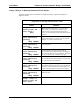
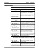
“Assign Relays to Warning and Fault Alarms” Menu
Display Comments
Assign “relays” to
warning alarms and
fault alarms→→
NEXT↓↓
Menu subgroup heading. Press → to access menu
items, press ↓ to scroll to next “Alarms” menu
subgroup. For each of the following menu items,
press → to scroll through and select the desired alarm
indicator.
system fault
alarm indicated by
(Nothing)
NEXT↓↓ CHANGE→→
“System fault” can be caused by a radar head fault, a
signal processor failure, a write error to non-volatile
memory, or a memory checksum error.
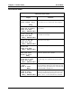
Radar head fault
alarm indicated by
(Nothing)
NEXT↓↓ CHANGE→→
Caused by partial or complete loss of control signals
from radar head.
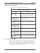
Waiting for echo
alarm indicated by
(Nothing)
NEXT↓↓ CHANGE→→
No echo is being received (within the range of
interest and above the minimum signal strength) but
the “lost echo” delay has not yet timed out. The signal
(if any) is outside of the acceptable range gate.
echo is lost
alarm indicated by
(Nothing)
NEXT↓↓ CHANGE→→
No echo is being received (within the range of
interest and above the minimum signal strength) and
the “lost echo” delay has timed out.
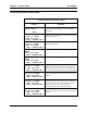
signal saturated
alarm indicated by
(Nothing)
NEXT↓↓ CHANGE→→
The signal strength of the strongest echo has
exceeded the maximum allowed level. If this problem
continues, increase the dielectric constant (page 5-2)
to reduce the gain applied to the microwave signal.
current max or min
alarm indicated by
(Nothing)
NEXT↓↓ CHANGE→→
Current output has reached the maximum or
minimum value.
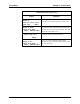
←←Exit from:
Assign “relays” to
warning alarms and
fault alarms
Press ← to Exit from this menu subgroup.