
Operating Manual

Accu-Wave Chapter 5 Radar Fine Tuning
TN Technologies 5-11
False Echo Management
Use the “False echo management” menu to correct false readings caused by unwanted
echoes.
False echo management has three primary approaches to eliminating false echoes. The first
is to constrain the set of candidate echoes to the smallest group that will reliably include
the desired echo. The second applies test criteria that can reject some of the unwanted
echoes. The third is to apply weighting factors to the remaining candidate echoes to
enhance the echo from the material while suppressing all other echoes.
Note: A good understanding of the echo report is necessary before using the
Radar Fine Tuning tools to deal with a difficult application.
Echo Report (View Echoes Being Processed)
The first item in the “False echo management” menu is the “view echoes being processed”
menu. Each screen in this menu describes one echo in the candidate set.
You should be able to correlate the echoes in the echo report with the physical layout of
your tank. First, identify which echo is from the material surface (based on its distance).
Echoes at distances greater than the echo from the surface of the material are normally the
result of multiple reflections or bounces. If the material is a low dielectric, such as
hydrocarbon, one of the more distant echoes may be from the bottom of the tank.
Echoes that appear at distances closer than the material surface are typically from pipes or
baffles. If you cannot associate echoes near the top of the tank with physical features, they
may be “phantom” echoes from multiple bounces in the entry nozzle or mounting
structure. The tools described in this chapter can be used to reject echoes caused by
mounting structures. The best approach is to minimize the number and signal strength of
these reflections by carefully mounting the Accu-Wave Sensor following the guidelines in
the Accu-Wave Installation and Maintenance Manual provided with your gauge.
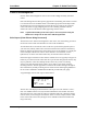
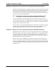
A typical display from the echo report is shown below:
echo 2 of 6 (#4)
Q1 = 180: 33.75 ft
Q2 = 45 : 22.11
SigStr
SWF = 0.500 NEXT↓
The first line of the display indicates that this echo report is for echo number 2 out of a
total of 6 candidate echoes. The “(#4)” notation indicates that echo number 4 has been
selected as the “best” echo. Note the echoes are numbered with echo 1 being the farthest
from the sensor, echo 2 being the next farthest, and so on. In this example, echo 6 would
be the closest echo to the sensor (among the set of candidate echoes that fall within the
range of interest).