
Operating Manual

Chapter 5 Radar Fine Tuning Accu-Wave
5-6 TN Technologies
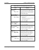
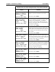
Response Time, Lost Echo, and Agitator Reject Setup
The “Response Time, Lost Echo, and Agitator Reject Setup” menus provide entries to
control the system response time, what action to take when the signal (echo) is lost, and the
response to a temporary loss or change in the echo.
When the Accu-Wave gauge is first turned on, the system begins processing the echoes
received from the microwave transmission to identify the true echo from the material
surface. Each time the gauge transmits a microwave signal, multiple echoes are received
by the sensor. The source of these echoes can include reflections from:
• the surface of the material (the proper or true echo)
• layers within the process material such as foam or oil–water interface
• streams of liquid filling the tank
• the tank bottom as seen through the process material
• agitator blades
• structural features in the tank
• multiple bounces from the various internal surfaces of the tank
• structures relating to the entry of the microwave signal into the tank
Echoes which fall within the range of interest (minimum to maximum distance) defined by
your setup entries for the primary measurement are included in the group of candidate
echoes, which are analyzed to select the “best” candidate for the echo from the surface.
If the location of the best candidate echo remains consistent (falls within a range gate) over
several transmissions, the system locks onto this echo as being the “true” echo from the
material surface. Echoes from subsequent transmissions are then analyzed. If the location
of the best candidate echo falls within a range gate centered on the average location of the
current, true echo (the present distance readout), the echo is considered valid, and the
distance measurement of this echo is used to update the measurement readout. If the echo
does not satisfy the range criteria, the group of echoes from a new transmission is
processed and a new echo report is generated. This process is repeated until the best
candidate echo passes the range gate criterion, or until a new “true” echo is confirmed at a
new location through its persistence.
Range Gate
The range gate defines the acceptance window which moves with the level (or distance)
readout. When the gauge is powered up or when the system switches to the “echo is lost”
mode, the range gate is in the not captured mode. After a certain number of “hits” (best
echo candidates which fall inside the range gate), the range gate switches to the captured
mode, that is, the gauge locks on to an echo as the true echo. When the range gate is in the
not captured mode, all “best candidate” echoes from successive transmissions are used to
update the measurement readout.
Once the range gate is in the captured mode, a “best candidate” echo is only used if:
• The echo distance falls within the range gate