
Operating Manual


Accu-Wave Chapter 5 Radar Fine Tuning
TN Technologies 5-1
Chapter 5 Radar Fine Tuning
The basic setup parameters entered via the “Set up Level,…” menu items (see Chapter 3)
establish the measurement range, or the region of interest, along with echo qualification
criteria. The measurement range defines the region over which the Accu-Wave gauge looks
for echoes. The qualification criteria are applied to the received echoes that fall within the
range of interest to identify the “most likely” echo from the surface of the process material.
In many applications, the measurement range and qualification criteria derived from the
basic setup parameters work fine and no further adjustments are required.
In more challenging apllications, additional fine tuning may be required for the Accu-Wave
gauge to lock onto the correct echo from the surface of the material. This chapter describes
the tools available in the Accu-Wave gauge designed to help deal with these more difficult
situations. In addition, this chapter describes how to override the default measurement
range (based on the basic setup parameters) and how to change the measurement
calibration.
Note: The Radar Fine Tuning menu structure has two layers of menu items, the
user layer and the service layer. The default user layer is adequate for
many applications.
The service layer provides several additional tools/menu items (tank
mapping, region weighting, and dynamic tracking) for handling
particularly difficult conditions. These additional tools are not supported
in software versions prior to Version 4.31. The service layer of tools is
intended to be used by an advanced user or by TN’s service personnel.
If you have difficulty configuring your gauge, contact the TN Technical
Support office for assistance.
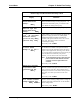
The Radar Fine Tuning section has four major menus groups.
1. Material Type and Measurement Head Setup
This menu allows you to enter information on the type of material the radar is
reflecting and on the measurement head mounting details. The assumed values for
these parameters will serve in most applications. However, if your unit is not
performing properly, you should enter the actual values for the parameters in this
menu.
2. Modify Range of Measurement
This menu allows you to override the measurement range. These entries will not
change the zero level, maximum level, or zero distance values you may have
already entered. You will be able to extend or constrain the measurement range to
something other than that implied by the basic entries.
3. Response Time, Lost Echo & Agitator Reject Setup
This menu deals with dynamic or time related issues. It provides entries to control
the response time (damping), the action taken when the signal (echo) is lost, and
the response to a temporary loss or change in the echo.