
Operating Manual

Chapter 3 Set up Level, Level Alarms, and Volume Accu-Wave
3-12 TN Technologies
Example: Low Limit Distance Alarm
This example illustrates how to set up a low limit distance alarm using a Set Point/Dead
Band alarm configuration. The primary measurement has been set up as distance with the
“Distance REF LINE to zero distance point” set to 4.5 ft and the “Distance REF LINE to
maximum distance point” set to 22.5 ft as illustrated in Figure 3.7.
It is desired to activate a process alarm when the distance of the process material surface
decreases to 3.0 ft (relative to the zero distance point) and to have the alarm clear when the
distance again increases to 5.0 ft. In addition, it is desired that the alarm clear point remain
a fixed distance from the set point if the set point value is later changed.
This is accomplished using a set point – dead band alarm configuration, with the set point
distance of 3.0 ft and with a dead band of 2.0 ft. This defines an “implicit clear point” at a
distance of 2.0 ft relative to the set point (or at a distance of 5.0 ft relative to the zero
distance point). If the set point is later changed, the implicit clear point will also change,
but will remain at a distance of 2.0 ft from the set point.
This is a low limit distance alarm since the set point distance is less than the clear point
distance. Note that this low limit distance alarm configuration is equivalent to the high
limit level alarm in the previous example. However, if the set points were changed, the
clear points would behave differently since a dead band configuration is used in this
example.
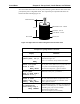
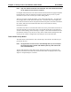
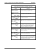
Figure 3.7 Low Limit Distance Alarm Using Set Point and Dead Band
Reference Line
Zero Distance
Maximum Distance
4.5 ft
22.5 ft
Dead Band
2.0 ft
Set Point - 3.0 ft
Implicit Clear
Point - 5.0 ft