
Operating Manual

Accu-Wave Chapter 3 Set up Level, Level Alarms, and Volume
TN Technologies 3-11
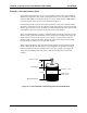
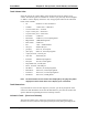
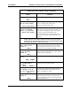
Since the measurement value for the set point (18.0 ft) is greater than the value of the clear
point (15.0 ft), this is a high limit alarm. The required steps to implement this alarm are
listed in the table following Figure 3.6.
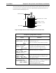
Figure 3.6 High Limit Level Alarm Using Set Point and Clear Point
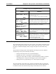
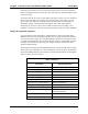
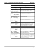
Example: Set up High Limit Level Alarm
Display Comments
Set up alarm 1
(Alarm point, etc.)→→
NEXT↓↓
Set up alarm 1 to be a high limit level alarm as
illustrated in Figure 3.6.
Press → to access the “Set up alarm” menu items.
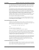
←←Exit alarm 1 setup
Alarm 1 set point
15.00 ft level
NEXT↓↓ HELP→→
Enter 15.0 followed by ↓ to enter the desired level for
the set point relative to the zero level point. The zero
level point was entered during the primary
measurement setup. Press ↓ again to continue.
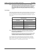
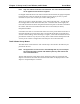
Alarm 1 clear based
on clr point
Chng to “dead band”→→
Continue as is.↓↓
Press the → to select a clear point configuration as
shown here. Then press ↓ to continue.
Alarm 1 clr point
13.00 ft level
{Makes alarm “Hi”
limit} NEXT↓↓ HELP→→
Enter 13.0 followed by ↓ to enter the desired level for
the clear point relative to the zero point level. The
display will indicte that this is a “Hi limit” alarm.
Press ↓ again to continue.
Alarm 1: ft level
is indicated by
controlling relay 1
NEXT↓↓ CHANGE→→
Select indicator for alarm 1. If relays are installed, the
default is “controlling relay 1,”. Other selections are:
controlling relay 2 (or 3 or 4 if installed)
measurement #1 display flash
Zero current output 1 (or 2 if installed)
Reference Line
Zero Level
Maximum Level - 18.0 ft
Zero Level
22.5 ft
Set Point - 15.0 ft
Clear Point - 13.0 ft