
Operating Manual

Chapter 8 Serial Ports, Contact Inputs & Special Fcts Accu-Wave
8-16 TN Technologies
Master Update Time
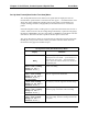
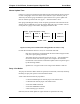
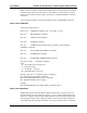
Gauges on a party–line transmit their data following the timing diagram shown in Figure
8.1. All of the gauges wait for the master unit to transmit a “sync” character (Ctrl-V,
ASCII 22). The master gauge transmits this synch character once per the update time
interval which is specified in the “Set up port … data transmission” menu.
Each gauge (including the master) counts off equally spaced time intervals based on the
window code (set identically for all of the gauges). When the current “window” interval
corresponds to a gauge’s unit number, that gauge transmits its data.
Start (sync character sent)
Unit 1 Unit 2 Unit 3 ...
Unit N
Window 1 Window 2 Window 3 ...
Window N
Figure 8.1 Party–Line Transmission Timing (Number of units, N ≤≤ 32)
For this data transmission scheme to work, two constraints must hold:
− Each slave unit must be programmed with the same window length, window
code, since equal spacing is assumed.
− The update time interval specified in the “Set up port … data transmission”
menu of the master unit must be greater than or equal to the combined
transmit time of the network. The minimum update interval required is given
by the following formula.
Update time = Largest window code x Largest Unit Number x 0.06 sec
Party–Line Modes
The party line has three distinct modes of operation, Unconnected, Connected, and Sleep.
Normally, the party line operates in the Unconnected mode.
A unit in Unconnected mode only responds to:
− a connect ESCAPE sequence with the proper unit–number suffix
− a command code with the proper unit–number suffix
− an all units SLEEP Command
− an all units WAKEUP Command
− a data streaming sync character
Otherwise, the unit sends updates at regular intervals as specified in the setup.
Window Time