
Operating Manual

Chapter 8 Serial Ports, Contact Inputs & Special Fcts Accu-Wave
8-8 TN Technologies
ANSI terminal: The gauge sends ANSI escape sequences for screen and cursor control
which are supported by ANSI terminals and by most PC-based communication packages.
This setup allows full access to the gauge menu system from the terminal. The arrow keys
on the terminal keypad behave in the same fashion as the intergral keypad on the
transmitter. The “X” or “x” keys on the remote computer or terminal correspond to the
“EXIT SETUP” key on the transmitter’s keypad.
VT100 terminal: This setup supports VT100 terminals and is similar to the ANSI terminal
setup.
Hand–Held terminal: This configuration supports the TN Hand Held Terminal (Model
9733) or the TNCOMM software emulation of the the Hand Held terminal.
Printer: This mode supports serial output to most printers. The ANSI screen–control
escape sequences are not available because they might be misinterpreted as printer set up
commands. Data is transmitted at the update interval you select in the “Set up port…”
menu items described below, or whenever you execute the “update data output” action
item (see page 7-6). This mode is output only, so the menu system is not available.
Blind mode: This is a special mode which supports access to the gauge via a user-written
program or script. The menu system is not available, rather the hexadecimal version of the
direct entry keyboard codes are used to set parameters. The gauge unit will echo a “>”
character (ASCII code 62) if the code is understood, otherwise it sends a “<” character
(ASCII code 60). This mode supports user-written scripts from within a terminal
emulation communications package to automate a setup or a data monitoring procedure.
Serial Port Related Menus
There are four menu subgroups used to set up and control the serial ports, two for the RS-
232 port and two for the RS-485 port. When you make entries for the parameters, the
actual port operation will not change until you save the entries (press “EXIT SETUP” to
save entries and return to the measurement display).
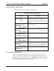
The serial port communication settings are configured using the “Modify Port 1 (RS232)
Configuration” and the “Modify Port 2 (RS485) Configuration” menus. The “Set up Port
1 (RS232) Data Transmission” and “Set up Port 2 (RS485) Data Transmission” menus
control the selection, formatting, and transmission of measurement data to the terminal or
printer.
The RS-232 and RS-485 configuration menus are very similar and the menu items
described in the following tables apply to both ports, except where noted.
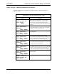
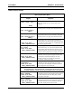
Modify Port 1 RS232 (Port 2 RS485) Configuration Menus
Use this menu to set up the baud rate and other communication parameters for each port.
The RS-232 menu items will display “RS232” or “Port 1 RS232” while the RS-485 menu
items will display “RS485” or “Port 2 RS485.” The necessary configuration information
for your communication device should be found in the user’s manual for the device.