
Operating Manual

Chapter 3 Set up Level, Level Alarms, and Volume Accu-Wave
3-10 TN Technologies
The next table presents those menu items specifically related to controlling a relay as an
alarm indicator. As noted in the Comments column, several of the menu items are only
displayed if options have been enabled in the “Special functions” menu, see “Special
Functions” on page 8-19.
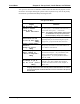
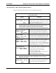
“Set up Alarm” Menu (continued)
Relay Indicator Related Items
Display Comments
alarm relay 1 set
delay 0 seconds
(0-255 s after
alarm) NEXT↓↓
Only displayed if “alarm relay delay times” have been
enabled in “Special functions” menu (see page 8-19).
Alarm condition must persist for the time entered for
alarm to be activated.
alarm relay 1 clear
delay 0 seconds
(0-255 s after alarm
has cleared) NEXT↓↓
Only displayed if “alarm relay delay times” have been
enabled in “Special functions” menu (see page 8-19).
Alarm clear condition must persist for the time
entered for alarm to be cleared.
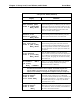
Do not use latching
mode with relay 1.
Change to “Do”→→
Continue as is.↓↓
Only displayed if relay latching has been enabled in
“Special functions” menu (see see page 8-19). When
latch mode is enabled for a relay, the relay remains in
alarm state even after the actual alarm is clear. The
relay is cleared by a “Clear alarms” command (see
page 7-3) or when system has been powered off.
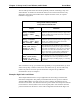
Relay 1 turns on
when alarm occurs.
Change to “off”→→
←←Exit alarm 1 setup.
Only displayed if a relay alarm indicator is selected as
the alarm indicator. Non-relay indicators include
zeroing current output, flashing display, or activating
commands.
After each alarm is set up, you will have the opportunity to set up another alarm, up to 16
alarms. Always keep a written record of how each alarm is set up. You can add a relay
board at any time. You can set up more alarms later using the “Set up additional
measurements” menu, see Chapter 4.
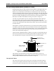
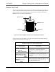
Example: High Limit Level Alarm
This example illustrates how to set up a high limit level alarm using a Set Point/Clear
Point alarm configuration. The primary measurement has been set up as level with the
“Distance REF LINE to zero level point” set at 22.5 ft and the “maximum level to be
measured” set at 18.0 ft. It is desired to activate a process alarm when the process material
level increases to 15.0 ft (relative to the zero level point) and to clear the alarm when the
process material level decreases to 13.0 ft. This configuration is illustrated in Figure 3.6.