
Operating Manual


Accu-Wave Chapter 1 Introduction
TN Technologies 1-5
drive alarms, or open and close switches. The alarms, user inputs, and selected outputs are
saved in non-volatile memory.
Automatic verification and error correction software continuously monitors system
operations. System faults can be programmed to set off alarms.
How to Use This Manual
For hardware mounting and installation wiring procedures refer to the “Accu-Wave
Installation Manual” provided with your gauge.
This manual, “Accu-Wave Operation Manual” describes how to set up and operate the
Accu-Wave gauge. Chapter 1, “Introduction,” provides an overview of the Accu-Wave
gauge and its features.
Note: This manual describes Version 4.31 of the Accu-Wave software. Earlier
versions of the software do not support all of the tools and functions
described in this manual.
We suggest that you read the appropriate chapters before you begin to set up your gauge.
Setting Up the Gauge
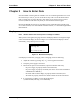
Chapter 2, “How to Enter Data,” introduces the menu system and how to enter or modify
the setup parameter values. The menu items are grouped into seven top level categories as
described below. Chapters 3 through 9 provide detailed information on the menu items in
each of these seven categories. For many applications, only the “Set up Level, Level
Alarms, and Volume” menu items are required to set up the Accu-Wave gauge.
Chapter 3, “Set up Level, Level Alarms, and Volume,” explains how to set up the primary
measurement (distance or level), measurement alarms, and the volume measurement
(optional).
Chapter 4, “Set up Additional Measurements,” explains how to set up the following
additional measurements:
− distance (outage), if the primary measurement is level
− level, if the primary measurement is distance
− percent distance
− percent level
− signal strength
− volume
− unfilled volume (ullage)
− percent full
− percent empty