
Instruction Manual


Operation Installation and Operation Handbook
2-14 2408 and 2404 Controller
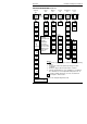
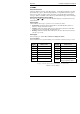
Name Description
AL
Alarm list
1 - - -
Alarm 1 setpoint value
2 - - -
Alarm 2 setpoint value
3 - - -
Alarm 3 setpoint value
4 - - -
Alarm 4 setpoint value
In place of dashes, the last three characters
indicate the alarm type. See alarm types
table:
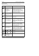
HY 1
Alarm 1 Hysteresis (display units)
HY 2
Alarm 2 Hysteresis (display units)
HY 3
Alarm 3 Hysteresis (display units)
HY 4
Alarm 4 Hysteresis (display units)
Lb t
Loop Break Time in minutes
diAG Enable Diagnostic alarms ‘no’ /
‘YES’
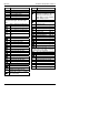
Alarm types table
-FSL
PV Full scale low alarm
-FSH
PV Full scale high alarm
-dEv
PV Deviation band alarm
-dHi
PV Deviation high alarm
-dLo
PV Deviation low alarm
-LCr
Load Current low alarm
-HCr
Load Current high alarm
-FL2
Input 2 Full Scale low alarm
-FH2
Input 2 Full Scale high alarm
-LOP
Working Output low alarm
-HOP
Working Output high alarm
-LSP
Working Setpoint low alarm
-HSP
Working Setpoint high alarm
4rAt
Rate of change alarm (AL 4 only)
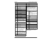
Atun
Autotune list
tunE
One-shot autotune enable
drA
Adaptive tune enable
drA.t
Adaptive tune trigger level in
display units. Range = 1 to 9999
Adc
Automatic Droop Compensation
(PD control only)
Name Description
Pid
PID list
G.SP
If Gain Scheduling has been
enabled (see Chapter 4), this
parameter sets the PV below
which ‘Pid.1’ is active and above
which ‘Pid.2’ is active.
SEt ‘Pid.1’ or ‘Pid.2’ selected
Pb Proportional Band (SEt 1)
(in display units)
ti Integral Time in secs (SEt 1)
td Derivative Time in secs (SEt 1)
rES Manual Reset (%) (SEt 1)
Hcb Cutback High (SEt 1)
Lcb Cutback Low (SEt 1)
rEL.C Relative Cool Gain (SEt 1)
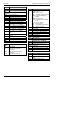
Pb2 Proportional Band (SEt 2)
ti2 Integral Time in secs (SEt 2)
td2 Derivative Time in secs (SEt 2)
rES.2 Manual Reset (%) (SEt 2)
Hcb2 Cutback High (SEt 2)
Lcb2 Cutback Low (SEt 2)
rEL.2 Relative Cool Gain (SEt 2)
The following three parameters are used for
cascade control. If this facility is not being
used, then they can be ignored.
FF.Pb
SP, or PV, feedforward propband
FF.tr
Feedforward trim %
FF.dv PID feedforward limits ± %
mtr
Motor list - see Table 4-3
tm
Valve travel time in seconds
In.t
Valve inertia time in secs
bAc.t
Valve backlash time in secs
mp.t
Minimum ON time of output pulse
U.br
Valve sensor break strategy