
Instruction Manual

Installation Installation and Operation Handbook
1-14 2408 and 2404 Controller
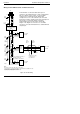
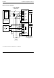
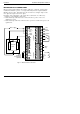
Example of Devicenet Wiring
To configure DeviceNet Communications see Chapter 6.
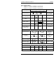
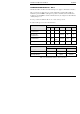
HA
HB
HC
HD
HE
HF
2400 Controller
(SLAVE)
Address 11
V+
CAN-H
CAN-L
Drain
V-
V+ 5
CAN-H 4
CAN-L 2
Drain 3
V- 1
Red
Wht
Blu
Blk
* Fit 121 resistor to
last instrument in the
chain
Network
Supply
24Vdc ( +
1%)
250mV p-p
Ripple
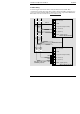
HA
HB
HC
HD
HE
HF
2400 Controller
(SLAVE)
Address N+1
V+
V-
V-
V+
Typical Interface
Card (MASTER)
Daisy chain to
further
instruments
121 terminating
resistor required if not
fitted internally
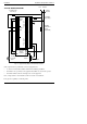
L
N
E
L
N
E
*