
Instruction Manual

Installation Installation and Operation Handbook
1-6 2408 and 2404 Controller
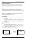
Wire Sizes
All electrical connections are made to the screw terminals at the rear of the controller. They
accept wire sizes from 0.5 to 1.5 mm
2
(16 to 22 AWG) and should be tightened to a torque of
0.4Nm (3.5lbin). If you wish to use crimp connectors, the correct size is AMP part number
349262-1. The terminals are protected by a clear plastic hinged cover to prevent hands, or
metal, making accidental contact with live wires.
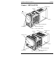
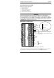
Rear terminal layouts
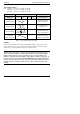
The rear terminal layouts are shown in Figures 1-5 and 1-6. The right-hand column carries
the connections to the power supply, digital inputs 1 and 2, alarm relay and sensor input. The
second and third columns from the right carry the connections to the plug-in modules. The
connections depend upon the type of module installed, if any. To determine which plug-in
modules are fitted, refer to the ordering code and wiring data on the controller side labels.
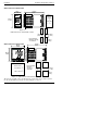
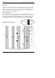
Model 2404 rear terminal layout
Figure 1-6 Rear terminal layout − Model 2404
RTD/Pt100
N
L
V+
V
I
V
-
Line
Neutral
Ground*
2D
2B
2
A
2C
3D
3B
3
A
3C
1D
1B
1
A
1C
M
O
D
U
L
E
1
M
O
D
U
L
E
3
M
O
D
U
L
E
2
HF
HD
HE
C
O
M
M
S
1
JF
JD
JE
C
O
M
M
S
2
Common
Input 1
Input 2
85 to 264Vac
LC
L
A
LB
AC
AA
AB
A
larm
relay
−
+
PV
−
T/C
HB
H
A
HC
JB
JA
JC
+
5B
5
A
4D
4B
4
A
4C
20 − 29Vac/dc
Ground
*
24
24
Low voltage supply
6D
6C
6B
5D
5C
6A