
Instruction Manual

Installation and Operation Handbook Configuration
2416 Controller 6-15
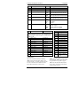
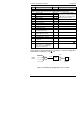
Name Description Values Meaning
CAL
Calibration
In this mode you can
1. Calibrate the instrument using a mV source -
rcAL
or ref source
cal.
2. Offset the calibration to account for errors in actual sensor
measurement and a ref sensor -
UCAL
or user calibration
3. Return to factory set calibration -
FACT
or factory set calibration.
rcAL
Calibration
point
nonE
No calibration
PV
Calibrate main Process Value input.
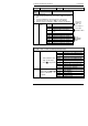
PV.2
Calibrate DC input, or PV 2.(not
2416)
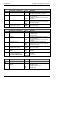
1A.Hi
Calibrate DC output high - Module 1
1A.Lo
Calibrate DC output low - Module 1
2A.Hi
Calibrate DC output high - Module 2
2A.Lo
Calibrate DC output low - Module 2
3A.Hi
Calibrate DC output high - Module 3
3A.Lo
Calibrate DC output low - Module 3
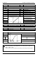
INPUT CALIBRATION
For ‘CAL’ = ‘PV’, or ‘PV.2’, the following parameters apply.
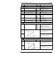
PV
PV Calibration Value
IdLE
Idle
mv.L
Select 0mV as the calibration point
mv.H
Select 50mV as the calibration point
V 0
Select 0Volt as the calibration point
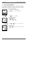
1. Select calibration value
V 10
Select 10V as the calibration point
2. Apply specified input
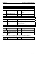
CJC
Select 0
o
C CJC calibration point
3. Press
to step to ‘GO’ rtd
Select 400Ω as the calibration point
HI 0
High impedance: 0Volt cal’n point
HI 1.0
High impedance: 1.0 Volt cal’n point
FACt
Restore factory calibration
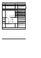
GO
Start calibration
no
Waiting to calibrate PV point
Select ‘YES’ with
or YES
Start calibration
Wait for calibration to
buSy
Busy calibrating
complete.
donE
PV input calibration completed
FAIL
Calibration failed
Go to User
calibration
table - See
also chapter 7
Go to input
Calibration table
Go to
DC Output
Calibration
table