
Instruction Manual

Installation and Operation Handbook Operation
2416 Controller 2-13
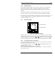
Continued from previous page:
The following parameters depend on the tYPE selected, as
shown below.
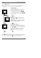
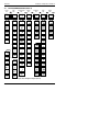
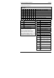
End rmP.r rmP.t dwEl StEP cALL
Hb
Holdback type: OFFLo Hior bAnd
tGt
Target setpoint for a ‘rmP’ or ‘StEP’ segment
rAtE
Ramp rate for a ‘rmP.r’ segment
dur
‘dwEl’ time / time to target for a ‘rmP.t’ segment
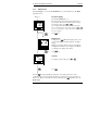
PrG.n
cALLed ProGram number
cYc.n
No. of cycles of cALLed program
outn
Event output: OFF/on (not 8-segment programmer)
SYnc
Not operational in 2416. Set to no.
End.t
End of prog − dwEl, RSEt, S OP
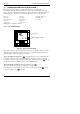
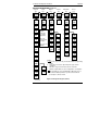
Name Description
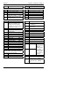
Alarm list
1 - - -
Alarm 1 setpoint value
2 - - -
Alarm 2 setpoint value
3 - - -
Alarm 3 setpoint value
4 - - -
Alarm 4 setpoint value
In place of dashes, the last three characters
indicate the alarm type as follows:
Note: It is possible to indicate only up to
four alarm conditions (known as soft
alarms). They can be “wired” to operate
relays within the limitations of the number of
output modules available. For more
information see Configuration - Chapter 6.
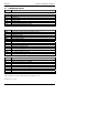
Name Description
-FSL
PV Full scale low alarm
-FSH
PV Full scale high alarm
-dEv
PV Deviation band alarm
-dHi
PV Deviation high alarm
-dLo
PV Deviation low alarm
-LCr
Load Current low alarm
-HCr
Load Current high alarm
-FL2
Not available in 2416
-FH2
Not available in 2416
-LOP
Working Output low alarm
-HOP
Working Output high alarm
-LSP
Working Setpoint low alarm
-HSP
Working Setpoint high alarm
4rAt
Rate of change alarm (AL 4
only)
HY 1
Alarm 1 Hysteresis (display
units)
HY 2
Alarm 2 Hysteresis (display
units)
HY 3
Alarm 3 Hysteresis (display
units)
HY 4
Alarm 4 Hysteresis (display
units)
Lb t
Loop Break Time in minutes
diAG Enable Diagnostic alarms ‘no’ /
‘YES’