
Instruction Manual


Installation and Operation Handbook Installation
2416 Controller 1-9
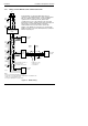
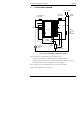
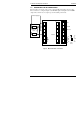
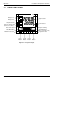
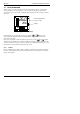
1.3 TYPICAL WIRING DIAGRAM
Fig 1-7 Typical wiring diagram, Model 2416 Controller
Safety requirements for permanently connected equipment state:
• A switch or circuit breaker shall be included in the building installation
• It shall be in close proximity to the equipment and within easy reach of the operator
• It shall be marked as the disconnecting device for the equipment.
Note: a single switch or circuit breaker can drive more than one instrument.
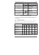
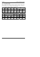
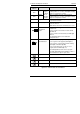
For logic drive capability see following chart:-
Comms
Neutral
Heating
power fuse
(load
dependent)
Line
Thermocouple
Cooling Power
Fuse 1A(T)
Controller
Fuse 2A(T)
Solid State
Relay
e.g. TE10
+
-
Snubber
Heater
JA
JF
B
HA
HB
HC
HD
HE
HF
1A
1B
2A
2B
3A
3B
L
N
V1
V+
V-
Cooling
solenoid
valve
Circuit
breaker