
Instruction Manual


Installation Installation and Operation Handboo
k
1-4 2416 Controller
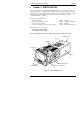
1.2 ELECTRICAL INSTALLATION
This section consists of five topics:
• Rear terminal layout
• Fixed connections
• Plug-in module connections
• Typical wiring diagram
• Motorised valve connections
All electrical connections are made to the screw terminals at the rear of the controller. These
screw terminals accept wire sizes from 0.5 to 2.5mm
2
(14 to 22 awg) and should be tightened
to a torque of 0.4 Nm (3.5 lb in). If you wish to use crimp connectors, we recommend AMP
part number 16500. These accept wire sizes from 0.5 to 1.5 mm
2
(16 to 22 AWG).
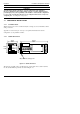
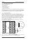
1.2.1 Rear Terminal Layout
Terminals are arranged in three columns at the rear of the controller. Each column is
protected by a clear plastic hinged cover to prevent hands or metal making accidental contact
with live wires. Viewed from the rear and with the controller upright, the right-hand column
carries the connections for the power supply and sensor input. The other two columns carry
the connections to the plug-in modules. The connections depend upon the type of module
installed, if any. To discover which plug-in modules are installed in your controller, please
refer to the ordering code and wiring data on the labels on the sides of the controller.
The rear terminal layout is shown below.
Note: The plug-in sleeve supplied with high voltage controllers are keyed to prevent a low
voltage unit being inserted into them.
Figure 1-4 Rear terminal layout
*The ground connection is provided as a return for internal EMC filters. It is not required for
safety purposes, but must be connected in order to satisfy EMC requirements.
+
PV
−
RTD/
Pt100
N
L
2B
1B
1A
3B
2A
3A
Line
Neutral
Ground*
+
−
T/C
VI
HD
M
O
D
U
L
E
3
V+
HE
V−
HF
H
A
HB
HC
C
O
M
M
S
M
O
D
U
L
E
2
M
O
D
U
L
E
1
85 to 264Vac
20 − 29Vac/dc
Ground
*
24
24
Low voltage supply