
Instruction Manual


Contents Installation and Operation Handbook
2 2416 Controller Issue 10 May 06 Applies to software version 4.0
4.3.4 Tune Error...................................................................................................... 4-6
4.4 motorised valve control.................................................................................... 4-7
4.5 Commissioning the Motorised Valve Controller............................................. 4-8
4.5.1 Adjusting the minimum on-time ‘mp.t’............................................................ 4-8
4.5.2 Inertia and backlash settings.......................................................................... 4-8
4.6 Gain scheduling................................................................................................ 4-9
5 Chapter 5 PROGRAMMER OPERATION..................................................... 5-1
6 Chapter 6 CONFIGURATION.......................................................................... 1
6.1 Selecting configuration level .............................................................................. 2
6.1.1 Password entry ................................................................................................. 2
6.2 Selecting a configuration parameter .................................................................. 3
6.2.1 Parameter names.............................................................................................. 3
6.3 Changing the passwords..................................................................................... 3
6.4 Leaving configuration level................................................................................. 3
6.5 navigation diagram (PART A).............................................................................. 4
6.6 confIGURATION PARAMETER TABLEs .............................................................. 6
7 Chapter 7 User Calibration.......................................................................... 7-1
7.1 WHAT IS the purpose of User calibration? ..................................................... 7-1
7.2 User Calibration Enable.................................................................................... 7-2
7.3 offset calibration............................................................................................... 7-3
7.4 Two-point calibration........................................................................................ 7-5
7.5 Calibration points and Calibration offsets ...................................................... 7-8
8 Chapter 8 LOAD CURRENT MONITORING AND DIAGNOSTICS ............. 8-1
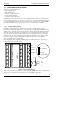
8.1 Example Wiring Diagram (For mode 1 & 2 operation).................................... 8-2
8.2 Operation........................................................................................................... 8-3
8.2.1 To Read Load Current (mode 2 only) ............................................................. 8-3
8.2.2 To Display Load Current Continuously in the Lower Readout (mode 2 only) .. 8-3
8.2.3 Display Modes................................................................................................ 8-3
8.2.4 How Heater Alarms Are Displayed ................................................................. 8-4
8.3 To Set The Alarm Trip Levels........................................................................... 8-5
8.4 Short Circuit SSR Alarm and Heater Fail Alarm.............................................. 8-5
8.5 relay outputs...................................................................................................... 8-5
8.6 TO CONFIGURE PDS LOAD CURRENT DIAGNOSTICS.................................. 8-6
8.7 To configure the Logic Module for PDS modes 1 or 2 ................................... 8-6
8.8 To Configure Low and High Current Trip Alarms ........................................... 8-8
8.9 To Attach Soft Alarms To A Relay Output ....................................................... 8-9
8.10 the scaling factor ............................................................................................ 8-10
8.10.1 To Adjust the Scaling Factor ................................................................... 8-10
Appendix A UNDERSTANDING THE ORDERING CODE ...................A-1
Appendix B SAFETY and EMC INFORMATION ..................................B-1
Appendix C TECHNICAL SPECIFICATION..........................................C-1
Appendix D RoHS STATEMENT ..........................................................D-1
“This product is covered by one or more of the following US Patents:
5,484,206; Additional patents pending.
PDSIO and INSTANT ACCURACY are trademarks of Eurotherm.”