
Instruction Manual

Installation and Operation Handbook Load Current Monitoring and Diagnostics
2408 and 2404 Controller D-7
TO CONFIGURE PDS LOAD CURRENT DIAGNOSTICS
Configuration of PDS load current diagnostics is in four parts:-
1. Configure the Logic Module for PDS Mode 1 or 2 operation. If the control device is a
contactor or standard SSR, configure the LA digital input for mode 5 operation.
2. Configure the Low and High Current trip alarms.
3. Attach the alarms to operate an output relay.
4. Set up the Scaling Factor.
First enter Configuration Level. See Chapter 5
TO CONFIGURE THE LOGIC MODULE FOR PDS MODES 1 OR 2
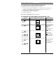
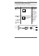
Do This This Is The Display You Should See Additional Notes
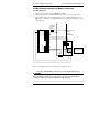
Press until the
1A Conf is
displayed
Press
to show
id
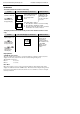
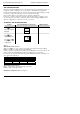
Press
to show
Func
Press or
to show SSr1 or
SSr 2 as required.
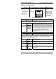
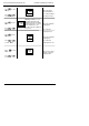
Press
to show
VAL.L
Press or
to show 0.0
This opens the
configuration list
associated with
module position 1A
This shows the
identity of the
module
The module identity
is log
ic output
This shows the
func
tion of module
The module function
is set to PDS mode
1
This is the lower PID
demand level
To set the minimum
PID signal to 0%
VAL.L
0.0
1A
Conf
id
Log
Func
SSr1