
Instruction Manual
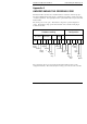

Installation and Operation Handbook Understanding The Ordering Code
2408 and 2404 Controller A-5
Part 2: Configuration
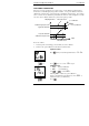
continued Digital
input 1
Digital
input 2
Control Power
feedback
Cooling Buttons Program
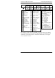
AM S2 XX XX XX MD XX
The example given in the coding is for 2408 PID controller, 85 to 264 Vac, logic heating,
relay cooling, low alarm relay, high alarm relay, RS485 Modbus comms, PDSIO setpoint
retransmission, type K thermocouple, 0 to 1000
o
C, Auto/manual select, second setpoint
select, manual button disabled.
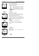
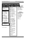
Digital inputs 1 & 2
XX Disabled AT Adaptive tune enable
AM Manual select FA Select full access level
SR Remote setpoint
select
RB Simulates UP button
S2 Second setpoint
select
LB Simulates DOWN button
EH Integral hold SB Simulates SCROLL
button
AC Alarm acknowledge PB Simulates PAGE button
RP Setpoint rate limit
enable
B1 Least sig. BCD dig.
RN Run program B2 2nd BCD digit
HO Hold program B3 3rd BCD digit
RE Reset program B4 4th BCD digit
RH Run/hold program B5 5th BCD digit
KL Keylock B6 Most sig. BCD digit
NT Run/Reset program SY Standby - ALL ops OFF
TN Reset/Run program SG Skip segment (without
changing SP)
HB Prog. holdback
enable
SC Program synch.
P2 PID2 select PV Select PV2
ST One-shot tune enable AG Advance to end of
segment (& step to target
setpoint)
M5 CTX (mode 5)
(input 2 only)
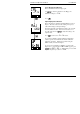
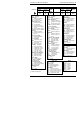
Options
Control action
XX Reverse acting (standard)
DP Direct acting PID control
Power feedback
XX Enabled on logic, relay &
triac heating
PD Feedback disabled
Cooling options
XX Linear cooling
CF Fan cooling
CW Water cooling
CL Oil cooling
CO On/off cooling
Front panel buttons
XX Enabled
MD Auto/man button disabled
MR Auto/man & run/hold
disabled
RD Run/hold button disabled
Programmer time units
XX Dwell & ramp in minutes
HD Dwell time in hours
HR Ramp rate in units/hour