
Instruction Manual

Understanding the Ordering Code Installation and Operation Handbook
A
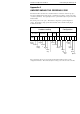
-2 2408 and 2404 Controller
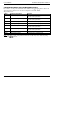
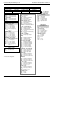
Part 1A: Hardware coding
Basic build Plug-in modules
Model number Function Supply voltage Module 1
2408 CC VH LH
* fitted unconfigured
Function
Standard PID control
CC Controller
CG 1 x 8 seg prog
CP 1 x 16 seg prog
P4 4 x 16 seg prog
CM 20 x 16 seg prog
Note 1
On/Off control
NF Controller only
NG 1 x 8 seg prog
NP 1 x 16 seg prog
N4 4 x 16 seg prog
NM 20 x 16 seg prog
Motorised valve control
VC Valve positioner (VP)
VG 1 x 8 seg prog
VP 1 x 16 seg prog
V4 4 x 16 seg prog
VM 20 x 16 seg prog
Note 1
Supply voltage
VH 85 to 264Vac
VL 20 to 29Vac/dc
Module 1
XX Not fitted
Relay: 2-pin
R2 Fitted unconfigured
RH PID heating
RU Valve raise output
Relay: change-over
R4 Fitted unconfigured
YH PID heating
RP Valve raise (note 6)
Or Alarm 1: select from table A
Logic: (Non-isolated)
L2 Fitted unconfigured
LH Heating output
M1 PDS heater break detect
(note 2
)
M2 PDS current monitoring
(note3)
Logic: (isolated)
LO Single logic output *
Triac
T2 Fitted unconfigured
TH Heating output
TU Valve raise output
DC control (isolated)
D4 Fitted unconfigured
H6 0-20mA PID heating
H7 4-20mA PID heating
H8 0-5V PID heating
H9 1-5V PID heating
HZ 0-10V PID heating
Digital I/O (unconfigured)
TK Triple contact input
TL Triple logic input
TP Triple logic output
Dual relay
RR Fitted unconfigured
RD PID heat + PID cool
RM Valve raise and lower
Dual triac
TT Fitted unconfigured
TD PID heat + PID cool
TM Valve raise and lower
Logic + relay
LR Fitted unconfigured
LD PID heat + PID cool
QC Mode 2 + cool
Logic + triac
LT Fitted unconfigured
GD PID heat + PID cool
QD Mode 2 + cool
Transducer P5
G3 5Vdc
G5 10Vdc
Table A : Alarm relay
functions
FH High alarm
FL Low alarm
DB Deviation band
DL Low dev. alarm
DH High dev alarm
Continued
next page
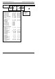
Model Number
2408 1/8 DIN Controller
2404 1/4 DIN Controller
Profibus units
2408f 1/8 DIN Controller
2404f 1/4 DIN Controller
Table B : DC
retransmission
D6 Fitted unconfigured
First character
V- PV retrans
S- Setpoint retrans
O- Output retrans
Z- Error retrans
Second character
-1 0-20mA
-2 4-20mA
-3 0-5V
-4 1-5V
-5 0-10V