
Instruction Manual

Installation and Operation Handbook Configuration
2408 and 2404 Controller 6-23
CONFIGURATION EXAMPLES
Transducer Power Supply
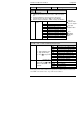
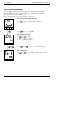
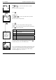
To configure the choice of output voltage:-
Do This The Display You Should
See
Additional Notes
1. Press
as many
times as necessary to
select the slot position in
which the transducer
power supply is fitted
The transducer power supply
can be fitted in slot positions
1 and 2.
The display will show 1A or
1b accordingly
2. Press
to read the
identity of the module
This is read only where:
SG.SU = Transducer Power
Supply
3. Press
(twice) to
read ‘Sens’
4. Press
and to
select ‘inv’ or ‘nor’
inv = 10Vdc nor = 5Vdc
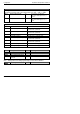
The Transducer Power
supply uses existing software
written for digital modules. A
list of parameters follow
which are not applicable to
this module.
1A
ConF
id
SG.SU
SEnS
inv