
Instruction Manual

Installation and Operation Handbook Configuration
2408 and 2404 Controller 6-19
3A/b/C
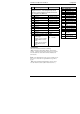
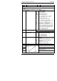
Module 3 configuration
As per module 2 configuration, plus ‘id’ = ‘dC.iP’
For ‘id’ = ‘dC.iP’ use this parameter table.
THIS INCLUDES THE SECOND PV FUNCTIONS
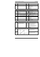
Func
Function
nonE
Function disabled
rSP
Remote Setpoint
Fwd.i
Feedforward input
rOP.h
Remote OP power max.
rOP.L
Remote OP power min.
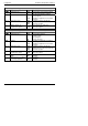
Hi
PV = The highest of iP.1 or iP.2
Lo
PV = The lowest of iP.1, or iP.2
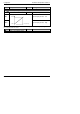
Ftn
Derived function, where
PV = (f.1 x iP1) + (f.2 x iP2).
‘F.1’ and ‘F.2’ are scalars which are found
in ‘ip-List’ of Operator Level
SEL
Select ip.1, or ip.2 via Comms, front
panel buttons, or a digital input
trAn
Transition of control between ip.1 and
ip.2. The transition region is set by the
values of ‘Lo.Ip’ and ‘Hi.Ip’, which are
found in ‘ip-List’ of Operator Level.
PV = ip.1 below ‘Lo.Ip’
PV = ip.2 above ‘Hi.Ip’
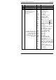
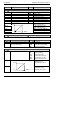
inpt
Input type
Refer to ‘ip Conf’ for all types, + the following:
HiIn
High Impedance (range = 0 to 2 volt)
CJC
Cold Junction
OFF
No cold junction compensation
Compensation
Auto
Automatic internal compensation
0
o
C
0
o
C external reference
45
o
C
45
o
C external reference
50
o
C
50
o
C external reference
imp
Sensor Break Impedance
Off
Disabled (applies to any input)
Caution:
If sensor break is disabled the controller
will not detect open circuit faults
Auto
Factory set
Hi
Impedance of input > 15KΩ
Hi.Hi
Impedance of input > 30KΩ
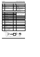
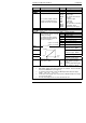
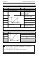
Linear Input Scaling − The next four parameters only appear if a linear input is chosen.
inP.L
Input value low
inP.H
Input value high
VAL.L
Displayed value low
VAL.H
Displayed value high
VAL.L
inP.HinP.L
VAL.H
Displayed Value
Electrical
Input