
Instruction Manual

Installation and Operation Handbook Configuration
2408 and 2404 Controller 6-11
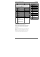
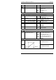
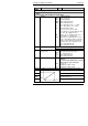
AL
Alarm configuration Values
The controller contains four ‘soft’ alarms, which are
configured in this list. Once configured, they can be
attached to a physical output as described in the alarm
relay configuration list, ‘AA Conf’.
AL1
Alarm 1 Type
see Table A
Ltch
Latching
no/YES/Evnt/mAn
*
bLoc
Blocking
no/YES
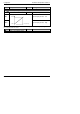
AL2
Alarm 2 Type
see Table A
Ltch
Latching
no/YES/Evnt/mAn
*
bLoc
Blocking
no/YES
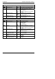
AL3
Alarm 3 Type
see Table A
Ltch
Latching
no/YES/Evnt/mAn
*
bLoc
Blocking
no/YES
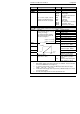
AL4
Alarm 4 Type
see Table A
Ltch
Latching
no/YES/Evnt/mAn
*
bLoc
Blocking
(not if ‘AL4’ = ‘rAt’)
no/YES
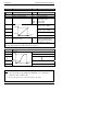
Sbr.t
Sensor break trip alarm
latching type.
Disable = process alarms
inhibited when in sensor
break
Enable = process alarms
shown when in sensor
break
En Enable
Dis Disable
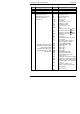
* Alarm Modes
‘no’ means that the alarm will be non-latching.
‘YES’ means that the alarm will be latched, with automatic
resetting. Automatic resetting means that if a reset is actioned
before the alarm has cleared, then it will automatically reset
when it clears.
Evnt’ means that the alarm is used to trip an external event. If
this option is selected the front panel alarm message will not
appear.
‘mAn’ means that the alarm will be latched, and can only be
reset after it has first cleared (called ‘manual reset mode’).
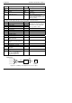
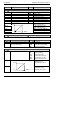
Table A - Alarm types
Value Alarm type
OFF
No alarm
FSL
PV Full scale low
FSH
PV Full scale high
dEv
PV Deviation band
dHi
PV Deviation high
dLo
PV Deviation low
LCr
Load Current low
HCr
Load Current high
FL2
Input 2 Full Scale low
FH2
Input 2 Full Scale
high
LOP
Working Output low
HOP
Working Output high
LSP
Working Setpoint low
HSP
Working Setpoint high
rAt
PV Rate of change
AL4 only
Ct.OP
CT open circuit
Ct.Sh
CT short circuit