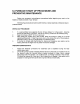
PID Controllers Models 2404/2408 Installation and Operation handbook ENG
Installation and Operation Handbook Contents MODELS 2408 and 2404 PID CONTROLLERS INSTALLATION AND OPERATION HANDBOOK Contents Page Chapter 1 INSTALLATION…………….…………………………… 1-1 Chapter 2 OPERATION…………………………………………….. 2-1 Chapter 3 ACCESS LEVELS………………………………………. 3-1 Chapter 4 TUNING…………………………………………………... 4-1 Chapter 5 PROGRAMMER OPERATION………………………… 5-1 Chapter 6 CONFIGURATION………………………………………. 6-1 Chapter 7 USER CALIBRATION…………………………………...
Contents Installation and Operation Handbook Issue 11 of this handbook applies to software version 4 and includes RoHS statement. Enhancements to Software Version 4 The following enhancements have been added to software versions 4. • Isolated Single Logic Output Module • Transducer Power Supply Module to provide 5 or 10Vdc to an external transducer.
Installation and Operation Handbook Installation Chapter 1 INSTALLATION Terminal covers Sleeve Ratchets Display screen Label Panel retaining clips Latching ears Panel sealing gasket Figure 1-1 2408 1/8 DIN controller Sleeve Terminal covers Ratchets Display screen Label Panel retaining clips Latching ears Panel sealing gasket Figure 1-2 2404 1/4 DIN controller 2408 and 2404 Controller 1-1
Installation Installation and Operation Handbook Outline dimensions Model 2408 48mm 1.89in 150mm 5.91in Panel cut-out 2408 OP 1 OP2 92 x 45mm 96mm 3.78in -0 +0.8 -0 +0.6 3.62x1.77in SP2 -0 +0.03 REM AUTO RUN MAN HOLD -0 +0.02 Figure 1-3 Outline dimensions of Model 2408 controller 10mm (0.4in) Recommended minimum spacing of controllers Outline dimensions Model 2404 96mm 3.78in 38mm (1.5in) (Not to scale) 150mm 5.91in 2404 OP 1 OP2 SP2 REM 96mm 3.
Installation and Operation Handbook Installation INTRODUCTION Models 2408 and 2404 are high stability, temperature or process controllers with self and adaptive tuning. They have a modular hardware construction which accepts up to three plugin Input/Output modules and two interface modules to satisfy a wide range of control requirements. Two digital inputs and an optional alarm relay are included as part of the fixed hardware build.
Installation Installation and Operation Handbook NEW SLEEVE DESIGN MKIII From Jan-03 an improved design of 1/8 DIN long sleeve is shipped with all new 2408 controllers and indicators. (The month and year of manufacture are shown in the last two pairs of digits of the instrument serial number). Details A new sealing gasket will be fitted onto the instrument bezel c. This gasket replaces the gasket which was moulded into the front of the sleeve of all previous instruments.
Installation and Operation Handbook Installation ELECTRICAL INSTALLATION This section consists of five topics: • Rear terminal layouts • Fixed connections • Plug-in module connections • Typical wiring diagrams • Motorised valve connections. WARNING You must ensure that the controller is correctly configured for your application. Incorrect configuration could result in damage to the process being controlled, and/or personal injury.
Installation Installation and Operation Handbook Wire Sizes All electrical connections are made to the screw terminals at the rear of the controller. They accept wire sizes from 0.5 to 1.5 mm2 (16 to 22 AWG) and should be tightened to a torque of 0.4Nm (3.5lbin). If you wish to use crimp connectors, the correct size is AMP part number 349262-1. The terminals are protected by a clear plastic hinged cover to prevent hands, or metal, making accidental contact with live wires.
Installation and Operation Handbook Installation Sensor input connections The connections for the various types of sensor input are shown below. Thermocouple Resistance thermometer mA input VI VI VI V+ V+ V+ V- V- V- Volts or mV inputs VI 2.49Ω current sense resistor V+ + V- - PV Fig 1-7 Sensor input connections PLUG-IN MODULE CONNECTIONS Module 1, 2 and 3 Module positions 1, 2 and 3 are plug-in modules.
Installation Installation and Operation Handbook Two terminal modules Note: Module 1 is connected to terminals 1A and 1B Module 2 is connected to terminals 2A and 2B Module 3 is connected to terminals 3A and 3B.
Installation and Operation Handbook Installation Four terminal modules Note: Module 1 is connected to terminals 1A, 1B, 1C and 1D Module 2 is connected to terminals 2A, 2B, 2C and 2D Module 3 is connected to terminals 3A, 3B, 3C and 3D Module type Terminal identity A Relay: changeover (2A, 264 Vac max.) DC control: Isolated (10V, 20mA max.
Installation Installation and Operation Handbook Module type Terminal identity A Isolated Logic Output Transducer Power Supply B C + + Possible functions D - This is a fully isolated module which can be fitted in all three module slots. It may be used for heating, cooling or events outputs up to 18Vdc at 20mA. This provides fully isolated 5 or 10Vdc to power external transmitters up to 20mA. It can be fitted in module slots 1 and 2.
Installation and Operation Handbook Installation COMMUNICATION MODULES 1 AND 2 All 2408 and 2404 controllers can be fitted with up to two plug-in communications modules. Only one of the two modules can be for serial communications and this will normally be installed in position COMMS 1 (although it is possible to install the serial communications module in position COMMS 2. Serial communications may be configured for either Modbus or EI bisynch protocol.
Installation Installation and Operation Handbook Wiring of 2-wire EIA-485 serial communications link PC Com TX RX RX TX 2-wire EIA-485 is a connection which allows up to 32 controllers to be multi-dropped from a single communications link over a distance of up to 1.2Km.
Installation and Operation Handbook Installation DeviceNet Instruments fitted with software versions 4 onwards can be fitted with DeviceNet communications. The following shows the wiring connections for DeviceNet. Terminal Reference CAN Color Label Chip Description HA V+ Red DeviceNet network power positive terminal. Connect the red wire of the DeviceNet cable here. If the DeviceNet network does not supply the power, connect to the positive terminal of an external 11-25 Vdc power supply.
Installation Installation and Operation Handbook Example of Devicenet Wiring 121 terminating resistor required if not fitted internally V+ 5 CAN-H 4 Drain Wht 3 CAN-L 2 V- 2400 Controller Red 1 Blu Blk Typical Interface Card (MASTER) HA V+ HB CAN-H HC Drain HD CAN-L HE V- HF (SLAVE) Address 11 2400 Controller Network Supply 24Vdc ( +1%) 250mV p-p Ripple HA V+ L N E L N V+ E HB HC * HD V- Daisy chain to further instruments HE V- HF (SLAVE) Address N+1 * Fit 121 resisto
Installation and Operation Handbook Installation ProfiBus Wiring Controllers supplied with model numbers 2408f and 2404f are fitted with ProfiBus communications modules fitted in the H slot. Further details of ProfiBus communications is given in Appendix E and the ProfiBus Communications handbook part number HA026290. This handbook can be downloaded from www.eurotherm.co.uk.
Installation Installation and Operation Handbook TYPICAL WIRING DIAGRAM Line Neutral Cooling Power Fuse 1A(T) Circuit breaker 1A 1B 1C 1D 2A 2B Logic heating output C O M M S Triac cooling 1 output JA HA L HB N HC B HD HE HF JF JA 2C 2D 3A 3B 3C 3D Controller Fuse 2A(T) LA Heating power fuse (load dependent) LB LC AA AB M O D U L E 3 C O M M S 2 AC B JD V1 JE V+ JF JF V- - Solid State Relay e.g.
Installation and Operation Handbook Installation Logic Drive Fan Out The logic outputs from the 2400 series controllers are capable of driving more than one solid state relay (SSR) in series or parallel. The following table shows the number of SSRs which can be driven depending on type of SSR. S = Series; P = Parallel.
Installation Installation and Operation Handbook MOTORISED VALVE CONNECTIONS Motorised valves will normally be wired either to dual relay, or dual triac, output modules installed in the Module 1 position, or to single channel relay and triac outputs installed in Module positions 1 and 2. In the latter case, the convention is to configure output 1 as the raise output and output 2 as the lower output. Depending on the configuration, control of the valve is achieved in one of three ways: 1.
Operation Installation and Operation Handbook Chapter 2 OPERATION This chapter has nine topics: • FRONT PANEL LAYOUTS • BASIC OPERATION • OPERATING MODES • AUTOMATIC MODE • MANUAL MODE • PARAMETERS AND HOW TO ACCESS THEM • NAVIGATION DIAGRAM • PARAMETER TABLES • ALARMS 2408 and 2404 Controller 2-1
Operation Installation and Operation Handbook FRONT PANEL LAYOUTS 2408 2408 OP OP 11 Output 1 OP 2 OP2 Output 2 Upper Lower readout Remote setpoint / comms (flashing) Setpoint 2 SP2 SP2 Auto mode REM REM Program running AUTO RUN MAN HOLD Auto/Man button Run/Hold Manual mode Program in Hold Page Scroll Down Up Button Button Button Button Figure 2-1 Model 2408 front panel layout 2404 2404 Output 1 OP 1 OP 1 Output 2 OP OP22 Upper readout Lower readout Remote setpoint/ comms(flashing) S
Operation Installation and Operation Handbook Button or indicator Name OP1 Output 1 When lit, it indicates that the output installed in module position 1 is on. This is normally the heating output on a temperature controller. OP2 Output 2 When lit, it indicates that the output installed in module position 2 is on. This is normally the cooling output on a temperature controller.
Operation Installation and Operation Handbook BASIC OPERATION Switch on the power to the controller. It runs through a self-test sequence for about three seconds and then shows the measured temperature, or process value, in the upper readout and the target value, called the setpoint, in the lower readout. This is called the Home display.
Operation Installation and Operation Handbook OPERATING MODES The controller has two basic modes of operation: • Automatic mode in which the output is automatically adjusted to maintain the temperature or process value at the setpoint. • Manual mode in which you can adjust the output independently of the setpoint. You toggle between the modes by pressing the AUTO/MAN button. The displays which appear in each of these modes are explained in this chapter.
Operation Installation and Operation Handbook AUTOMATIC MODE You will normally work with the controller in automatic mode. If the MAN light is on, press the AUTO/MAN button to select automatic mode. The AUTO light comes on. Power on The Home display Check that the AUTO light is on. The upper readout shows the measured temperature. The lower readout shows the setpoint. To adjust the setpoint up or down, press or .
Operation Installation and Operation Handbook MANUAL MODE If the AUTO light is on, press the AUTO/MAN button to select manual mode. The MAN light comes on. Power on The Home display Check that the MAN light is on. The upper readout shows the measured temperature, or process value. The lower readout shows the % output. To adjust the output, press or . (Note: If Output Rate Limit has been enabled, then the lower readout will show the working output.
Operation Installation and Operation Handbook PARAMETERS AND HOW TO ACCESS THEM Parameters are settings, within the controller, that determine how the controller will operate. For example, alarm setpoints are parameters that set the points at which alarms will occur. For ease of access, the parameters are arranged in lists as shown in the navigation diagram on Pages 2-10 and 2-11.
Operation Installation and Operation Handbook Parameter names In the navigation diagram, each box shows the display for a selected parameter. The Operator parameter tables, later in this chapter, list all the parameter names and their meanings. The navigation diagram shows all the parameters that can, potentially, be present in the controller. In practice, a limited number of them appear, as a result of the particular configuration.
Operation Installation and Operation Handbook NAVIGATION DIAGRAM (PART A) (The parameters that appear depend upon how the controller has been configured) Programmer List(1) Home List Run List(1) 20.0 run ProG 20.0 PrG PrG.n OP StAt Hb 20.0 o C 100.0 m-A Auto AmPS 5 C.id 1 LiSt 1 run PSP 20 CYC SEG 1 5.0 PrG.t no out.n OFF SYnc no SEG.d YES 2-10 OFF Hb V 20 rmP.U Hour PID List Pid mtr 1---2 tunE G.SP tm 2---2 drA SEt In.t 100 LiSt OFF LiSt 500 Pid.
Operation Installation and Operation Handbook NAVIGATION DIAGRAM (PART B) Input List Output List SP iP oP SSEL FiLt OP.Lo L-r FLt.2 SP 1 CAL Setpoint List LiSt SP 1 Loc 20.0 SP 2 0.0 sp3 to sp16 if configured rm.SP LiSt OFF OFF FACt The parameters that follow depend upon the controller configuration. Refer to the parameter table. They cover: user calibration & the 2nd PV input fiunctions. 0.0 rmt.t 0.0 Comms List Information List Access List cmS inFo ACCS di SP codE OP.
Operation Installation and Operation Handbook PARAMETER TABLES Name Description Home list Home Measured value and Setpoint % Output level OP Target setpoint (if in Manual mode ) SP Auto-man select m-A Heater current (With PDSIO mode 2) AmPS Customer defined identification number C.id + Extra parameters, if the ‘Promote’ feature has been used (see Chapter 3, Edit Level). run PrG StAt PSP CYC SEG StyP SEG.t tGt rAtE PrG.t FASt out.
Operation Installation and Operation Handbook Name Description ProG Program edit list − Present only in setpoint programming controller. For a fuller explanation of these parameters refer to Chapter 5 PrG.n Select program number (Only on 4, or 20, program versions) Hb Holdback type for the program as a whole (if configured)(OFF, Lo, Hi, or bAnd) Holdback value (in display units) Hb V rmP.U Ramp units (SEc, min, or Hour) [for both rmP.r and rmP.t type segments] dwL.
Operation Installation and Operation Handbook Name Description Name AL Alarm list Alarm 1 setpoint value Alarm 2 setpoint value Alarm 3 setpoint value Alarm 4 setpoint value Pid G.SP 1--2--3--4--- In place of dashes, the last three characters indicate the alarm type. See alarm types table: HY 1 HY 2 HY 3 HY 4 Lb t Alarm Alarm Alarm Alarm diAG Enable Diagnostic alarms ‘no’ / ‘YES’ -FSL -FSH -dEv -dHi -dLo -LCr -HCr -FL2 -FH2 -LOP -HOP -LSP -HSP 4rAt Atun tunE drA drA.
Operation Installation and Operation Handbook Name Description Name SP Setpoint list SSEL Select SP 1 to SP16, depending on configuration L-r Local (Loc) or remote (rmt) setpoint select SP 1 Setpoint one value SP 2 Setpoint two value Input list - continued iP The next 3 parameters appear if User Calibration has been enabled. (Refer to Chapter 7.) By default they are hidden when in Operator level.
Operation Name Installation and Operation Handbook Description Output list oP Does not appear if Motorised Valve control configured. Low power limit (%) OP.Lo High power limit (%) OP.Hi Output Rate Limit (% per sec) OPrr Forced output level (%) FOP Heat cycle time (0.2S to 999.9S) CYC.H Heat hysteresis (display units) hYS.H Heat output min. on-time (secs) ont.H Auto (0.05S), or 0.1 - 999.9S Cool cycle time (0.2S to 999.9S) CYC.C Cool hysteresis (display units) hYS.C Cool output min. on-time (secs) ont.
Operation Installation and Operation Handbook ALARMS Alarm annunciation Alarms are flashed as messages in the Home display. A new alarm is displayed as a double flash followed by a pause, old (acknowledged) alarms as a single flash followed by a pause. If there is more than one alarm condition, the display cycles through all the relevant alarm messages. Table 2-1 and Table 2-2 list all of the possible alarm messages and their meanings.
Operation Installation and Operation Handbook Diagnostic alarms These indicate that a fault exists in either the controller or the connected devices. Display shows What it means What to do about it EE.Er Electrically Erasable Memory Error: The value of an operator, or configuration, parameter has been corrupted. This fault will automatically take you into Configuration level. Check all of the configuration parameters before returning to Operator level.
Operation Installation and Operation Handbook no.io No I/O None of the expected I/O modules is fitted. This error message normally occurs when preconfiguring a controller without installing any of the required I/O modules. rmt.F Remote input failure. Either the PDSIO input, or the remote DC input, is open or short circuit Check for open, or short circuit wiring on the PDSIO, or remote DC, input. LLLL Out of range low reading Check the value of the input.
Operation 2-20 Installation and Operation Handbook 2408 and 2404 Controller
Installation and Operation Handbook Access Levels Chapter 3 ACCESS LEVELS This chapter describes the different levels of access to the operating parameters within the controller. There are three topics: • THE DIFFERENT ACCESS LEVELS • SELECTING AN ACCESS LEVEL • EDIT LEVEL THE DIFFERENT ACCESS LEVELS There are four access levels: • Operator level, which you will normally use to operate the controller. • Full level, which is used to commission the controller.
Access Levels Installation and Operation Handbook SELECTING AN ACCESS LEVEL Access to Full, Edit or Configuration levels is protected by a password to prevent unauthorised access. If you need to change the password, see Chapter 6, Configuration. Access list header Press until you reach the access list header ‘ACCS’. Press Password entry The password is entered from the ‘codE’ display. Enter the password using or .
Installation and Operation Handbook Access Levels Level selection The ‘Goto’ display allows you to select the required access level. Use and to select from the following display codes: OPEr: Operator level FuLL: Full level Edit: Edit level conF: Configuration level Press If you selected either ‘OPEr’, ‘FuLL’ or ‘Edit’ level you will be returned to the ‘ACCS’ list header in the level that you chose. If you selected ‘conF’, you will get a display showing ‘ConF’ in the upper readout (see below).
Access Levels Installation and Operation Handbook EDIT LEVEL Edit level is used to set which parameters you can view and adjust in Operator level. It also gives access to the ‘Promote’ feature, which allows you to select and add (‘Promote’) up to twelve parameters into the Home display list, thereby giving simple access to commonly used parameters. Setting operator access to a parameter First you must select Edit level, as shown on the previous page.
Installation and Operation Handbook Tuning Chapter 4 TUNING Before tuning, please read Chapter 2, Operation, to learn how to select and change a parameter. This chapter has five topics: • • • • • WHAT IS TUNING? AUTOMATIC TUNING MANUAL TUNING COMMISSIONING OF MOTORISED VALVE CONTROLLERS GAIN SCHEDULING WHAT IS TUNING? In tuning, you match the characteristics of the controller to those of the process being controlled in order to obtain good control.
Tuning Installation and Operation Handbook AUTOMATIC TUNING Two automatic tuning methods are provided in the 2408 and 2404: • A one-shot tuner, which automatically sets up the initial values of the parameters listed in Table 4-1 on the previous page. • Adaptive tuning, which continuously monitors the error from setpoint and modifies the PID values, if necessary. One-shot Tuning The ‘one-shot’ tuner works by switching the output on and off to induce an oscillation in the measured value.
Installation and Operation Handbook Tuning Typical automatic tuning cycle Temperature Setpoint Time Calculation of the cutback values Low cutback and High cutback are values that restrict the amount of overshoot, or undershoot, that occurs during large step changes in temperature (for example, under start-up conditions). If either low cutback, or high cutback, is set to ‘Auto’ the values are fixed at three times the proportional band, and are not changed during automatic tuning.
Tuning Installation and Operation Handbook MANUAL TUNING If for any reason automatic tuning gives unsatisfactory results, you can tune the controller manually. There are a number of standard methods for manual tuning. The one described here is the Ziegler-Nichols method. With the process at its normal running temperature: 1. Set the Integral Time ‘ti’ and the Derivative Time ‘td’ to OFF. 2. Set High Cutback and Low Cutback, ‘Hcb’ and ‘Lcb’, to ‘Auto’. 3.
Installation and Operation Handbook Tuning Setting the cutback values The above procedure sets up the parameters for optimum steady state control. If unacceptable levels of overshoot or undershoot occur during start-up, or for large step changes in temperature, then manually set the cutback parameters ‘Lcb’ and ‘Hcb’. Proceed as follows: 1. Set the low and high cutback values to three proportional bandwidths (that is to say, Lcb = Hcb = 3 x Pb). 2.
Tuning Installation and Operation Handbook Integral action and manual reset In a full three-term controller (that is, a PID controller), the integral term ‘ti’ automatically removes steady state errors from the setpoint. If the controller is set up to work in two-term mode (that is, PD mode), the integral term will be set to ‘OFF’. Under these conditions the measured value may not settle precisely at setpoint.
Installation and Operation Handbook Tuning MOTORISED VALVE CONTROL The 2408 and 2404 can be configured for motorised valve control as an alternative to the standard PID control algorithm. This algorithm is designed specifically for positioning motorised valves.
Tuning Installation and Operation Handbook COMMISSIONING THE MOTORISED VALVE CONTROLLER The commissioning procedure is the same for both bounded and boundless control modes, except in bounded mode you must first calibrate the position feedback potentiometer, as described in the section below. Proceed as follows: 1. Measure the time taken for the valve to be raised from its fully closed to its fully open position and enter this as the value in seconds into the ‘tm’ parameter. 2.
Installation and Operation Handbook Tuning 5. Press or to turn ‘PCAL’ to ‘on’. 6. Press and the upper readout indicates ‘Pot’. 7. Press or to get to ‘Pot-3A.Hi’. (Assuming that the Potentiometer Input Module is in module position 3.) 8. Press to go to ‘GO-no’. 9. Press or to see ‘GO-YES’, which starts the calibration procedure. 10. Calibration is complete when the display returns to ‘GO-no’. 11. Press and together to return directly to the Operator level. 12. The controller should still be in Manual mode.
Tuning Installation and Operation Handbook GAIN SCHEDULING Gain scheduling is the automatic transfer of control between one set of PID values and another. In the case of the 2408 and 2404 controllers, this is done at a presettable process value. It is used for the more difficult to control processes which exhibit large changes in their response time or sensitivity at, for example, high and low temperatures, or when heating or cooling. The 2408 and 2404 has two sets of PID values.
Installation and Operation Handbook Programmer Operation Chapter 5 PROGRAMMER OPERATION This chapter deals with the setpoint programming option. All 2408 / 2404 instruments have a basic 8-segment programmer built-in as standard. This facility must be enabled by the user, as explained in the section, Configuring the Programmer. Other programmer versions are listed below, and have 16-segments in each program.
Programmer Operation Installation and Operation Handbook WHAT IS SETPOINT PROGRAMMING? Many applications need to vary temperature, or process value, with time. Such applications need a controller which varies a setpoint as a function of time; all 2408 and 2404 models can do this. The setpoint is varied by using a setpoint program.
Installation and Operation Handbook Programmer Operation There are five different types of segment: Ramp The setpoint ramps linearly, from its current value to a new value, either at a set rate (called ramp-rate programming), or in a set time (called time-to-target programming). You must specify the ramp rate or the ramp time, and the target setpoint, when creating or modifying a program. Dwell The setpoint remains constant for a specified period.
Programmer Operation Installation and Operation Handbook PROGRAMMER STATES The programs have five states: Reset, Run, Hold, Holdback and End. State Description Indication Reset In Reset, the programmer is inactive and the controller behaves as a standard controller, with the setpoint determined by the value set in the lower readout. Both the RUN and HOLD lights are OFF Run In Run, the programmer varies the setpoint according to the active program.
Installation and Operation Handbook Programmer Operation RUNNING A PROGRAM FROM THE RUN LIST The Run List From the Home display, press header. until you reach the ‘run’ list Press Program number This display only appears on programmers that can store more or to select the required program than one program. Use number, from 1 to 4, or 1 to 20, depending on the particular controller. Alternatively, the program number can be selected remotely, using digital inputs on the rear terminals.
Programmer Operation Installation and Operation Handbook RUNNING A PROGRAM USING THE RUN/HOLD BUTTON If you are using a 4, or 20, program version of the controller, you must first select the number of the program that you want to run. Do this in the ‘run’ list − see the previous topic, Running a program from the Run list.
Installation and Operation Handbook Programmer Operation ‘Lo’ − Deviation Low Holdback holds the program back when the process variable deviates below the setpoint by more than the holdback value. ‘Hi’ − Deviation High Holdback holds the program back when the process variable deviates above the setpoint by more than the holdback value. ‘bAnd’ − Deviation Band Holdback is a combination of the two.
Programmer Operation Installation and Operation Handbook CONFIGURING THE PROGRAMMER When first installing a programmer you should check that the configuration conforms to your requirement. Configuration defines: • the number of stored programs (multi-programmer only) • the holdback strategy • the power fail strategy • the servo type • if event outputs are available (not 8-segment programmer) • if program synchronisation is available.
Installation and Operation Handbook Programmer Operation Power fail strategy Use or • cont: • rmP.b: • rSEt: to select Continue from last setpoint Ramp from PV to setpoint at last ramp rate Reset the program. Press Servo type Use or • to.PV: • to.
Programmer Operation Installation and Operation Handbook CONFIGURING DIGITAL INPUTS TO SELECT PROGRAM NUMBER The program number can be selected by external BCD inputs from, for example, a thumbwheel switch. The appropriate number of digital inputs must be installed in the controller and be configured for this function - see Chapter 6, Configuration. To invoke this mode of operation, the parameter ‘bcd’ in ‘inst-Conf’ must be set to ‘PrOg’. Press bcd PrOG 5-10 Use the until you reach ‘bcd’.
Installation and Operation Handbook Programmer Operation CREATING A NEW PROGRAM, OR MODIFYING AN EXISTING ONE The only difference between creating a new program, and modifying an existing one, is that a new program starts with all its segments set to End in the tYPE parameter. The procedure for both consists of setting up the parameters in the PrOG list of the Operator Navigation Diagram shown in Chapter 2.
Programmer Operation Installation and Operation Handbook Ramp units Use or • Sec • min • Hour to select: Press Dwell units Use or • Sec • min • Hour to select: Press Number of program cycles Use or to set the number of program cycles required from 1 to 999, or ‘cont’ for continuous cycling. Press Segment number Use or to select the number, from 1 to 16. (1 to 8 in 8-segment programmers) The parameters that follow ‘SEG.n’ set up the characteristics of the individually-selected segment number.
Installation and Operation Handbook Programmer Operation Segment type Select the segment type using or : Ramp to a new setpoint at a set rate • rmP.r: • rmP.t: Ramp to a new setpoint in a set time Dwell for a set time • dwEl: • StEP: Step to a new setpoint Call another program as a subroutine • cALL: • (only available in multi-program controllers) End: Make this segment the end of the program. Press The parameters that follow ‘tYPE’ depend on the type of segment selected as shown in the table below.
Programmer Operation Installation and Operation Handbook Ramp rate Ramp rate for ‘rmP.r’ segments Using or , set a value for the ramp rate, ranging from 0.0 to 999.9. The units are the ramp units (rmP.U) set earlier in this sequence. Press Duration time Time for a ‘dwEl’ segment, or time to target for a ‘rmP.t’ segment. Set the time using or . You have set the units earlier in this sequence. [‘dwL.U’ defines the units for ‘dwEl’ segments: ‘rmP.U’ defines the units for ‘rmP.t’ segments.
Installation and Operation Handbook Programmer Operation Event output 1 (16-segment programmers only) Appears in all segments, except ‘cALL’ segments. Use or to set output 1: • OFF: Off in the current segment On the current segment. • on: Press Further event outputs (16-segment programmers only) Up to eight (8) event outputs may appear in this list where ‘n’ = event number. Pressing will step through all the remaining event outputs.
Programmer Operation Installation and Operation Handbook Power Value [End Segment] Use or to set the power value in the range ±100.0%. This power level is clipped by the parameters ‘OP.Hi’ and ‘OP.Lo’ before being applied to the process. Note: In programmer/controller software versions 3.56 onwards this parameter has been replaced by a parameter End.P which appears at the end of the Output List, see Chapter 2 Press 5-16 to return to the ProG-LiSt header.
Installation and Operation Handbook Configuration Chapter 6 CONFIGURATION This chapter consists of six topics: • SELECTING CONFIGURATION LEVEL • LEAVING CONFIGURATION LEVEL • SELECTING A CONFIGURATION PARAMETER • CHANGING THE PASSWORDS • NAVIGATION DIAGRAM • CONFIGURATION PARAMETER TABLES. In configuration level you set up the fundamental characteristics of the controller. These are: • The type of control (e.g.
Configuration Installation and Operation Handbook SELECTING CONFIGURATION LEVEL There are two alternative methods of selecting Configuration level: • If you have already powered up, then follow the access instructions given in Chapter 3, Access levels. • Alternatively, press and together when powering up the controller. This will take you directly to the ‘ConF’ password display.
Installation and Operation Handbook Configuration LEAVING CONFIGURATION LEVEL To leave the Configuration level and return to Operator level Press display appears. Alternatively, pressing and until the ‘Exit’ together will take you directly to the ‘Exit’ display. Use or to select ‘YES’. After a two-second delay, the display will blank and revert to the Home display in Operator level.
Configuration Installation and Operation Handbook NAVIGATION DIAGRAM (PART A) Instrument Process Value Input Config Config Config iP Setpoint Config SP inSt PV CtrL unit inPt nSP Act dEc.P CJC CooL rnG.L Alarms Config AL Programmer Logic inputs Config Config PROG LA/b AL1 PtyP id rm.tr Ltch HbAc Func imp m.tr bLoc Pwr.F inp.L Pr.tr AL2 Srvo inp.H rmP.U Ltch out dtYP VaL.L rmt bLoc SYnc r-h VaL.H ConF Pid rEv Lin ti.
Installation and Operation Handbook Configuration NAVIGATION DIAGRAM (PART B) Alarm relay Comms 1 Config Config AA ConF HA ConF id id Func Func dIG mod SEnS bAud rELy nor cmS 9600 Prty nonE rES FuLL deLY no Comms 2 Config JA ConF id PdS Func SP.oP VAL.L 0 VAL.H 100 Module 1 Module 2 Module 3 Module 4(2) Custom(3) Config(1) Config(1) Config(1) Config Config 1A 3A 4A CUSt id id id in 1 Func Func Func UAL.1 VAL.L inpt VAL.L in 2 VAL.H imp VAL.H UAL.
Configuration Installation and Operation Handbook NAVIGATION DIAGRAM (PART C) Calibration Config Password Config CAL PASS cAL ACC.P UCAL cnF.P ConF nonE no ConF Exit no 1 2 pt1.L 0 pt1.H 0 OF1.L 0.0 OF1.H 0.0 pt2.L 0 pt2.H 0 OF2.L 0.0 OF2.H 0.0 Fig 6.
Installation and Operation Handbook Configuration CONFIGURATION PARAMETER TABLES Name Description inSt CtrL Instrument configuration Control type Values Meaning Pid On.OF VP PID control On/off control Boundless motorised valve control - no feedback required Bounded motorised valve control - feedback required Reverse acting Direct acting Linear Oil (50mS minimum on-time) Water (non-linear) Fan (0.5S minimum on-time) On/off cooling Seconds, OFF to 9999 Minutes, OFF to 999.
Configuration Installation and Operation Handbook Name Description Values Meaning pV unit Process value config Instrument units 0 dec.p Decimal places in the displayed value rng.L Range low rng.h Range high Celsius Fahrenheit Kelvin Display units blanked None One Two Low range limit. Also setpoint limit for alarms and programmers High range limit. Also setpoint limit for alarms and programmers C F 0 k none nnnn nnn.n nn.nn 0 Notes: 1.
Installation and Operation Handbook Name iP inPt Description Input configuration Input type Configuration Values Meaning J thermocouple K thermocouple L thermocouple R thermocouple (Pt/Pt13%Rh) B thermocouple (Pt30%Rh/Pt6%Rh) N thermocouple T thermocouple S thermocouple (Pt/Pt10%Rh) PL 2 thermocouple Custom downloaded t/c (default = type C) 100Ω platinum resistance thermometer Linear millivolt Linear voltage Linear milliamps Square root volts Square root milliamps * see CUST List.
Configuration Installation and Operation Handbook Name Description Values Meaning SP nSP Setpoint configuration Number of setpoints 2, 4, 16 Select number of setpoints available rm.tr Remote Tracking m.tr Pr.tr rmP.U rmt 6-10 OFF trAc Manual Track OFF trAc Programmer Track OFF trAc Setpoint rate limit units PSEc Pmin PHr Remote setpoint configuration nonE SP Loc.t rmt.
Installation and Operation Handbook AL Alarm configuration Configuration Values The controller contains four ‘soft’ alarms, which are configured in this list. Once configured, they can be attached to a physical output as described in the alarm relay configuration list, ‘AA Conf’.
Configuration Installation and Operation Handbook The following parameters apply if the standard 8-segment programmer is to be configured. PROG PtyP Programmer configuration Programmer type HbAc Holdback Values nonE 1 SEG ProG Pwr.F Power fail recovery Srvo Starting setpoint of a program (Servo point) cont rmP.b rSEt to.PV to.SP Meaning Programmer disabled (factory setting) 8-segment programmer enabled Holdback is individually selectable in each segment.
Installation and Operation Handbook Name Description LA LB Digital input 1/2 configuration Identity id Function of input Func The function is active when the input has a contact closure to the common terminal - LC These BCD inputs are used to select either a program number or the setpoint number according to the setting of the parameter ‘bcd’ in the ‘inSt’ configuration list Configuration Values LoG.i nonE mAn rmt SP.2 Pid.2 ti H tunE drA Ac.AL AccS Loc.
Configuration Installation and Operation Handbook Name Description AA id Func Alarm relay configuration Identity Function SEnS Digital output sense Values Meaning rELy nonE dIG nor Relay output No function Digital output Normal (output energises when TRUE, e.g. program events) Inverted (output de-energises when TRUE, e.g. alarms) inv The following digital events appear after ‘SEnS’. Any one, or more, of the events can be combined on to the output (see Fig.
Installation and Operation Handbook Configuration Name Description Values Meaning HA Comms 1 module config Identity of the module installed cmS id PDS PDS.i dnET EIA-232, or 2-wire EIA-485, or 4-wire EIA-485 comms PDS retransmission PDS input DeviceNet For ‘id’ = ‘cms’ (Digital communications) use this parameter table: Func Function bAud Baud Rate dELy Delay - quiet period, required by some comms adaptors Modbus protocol mod Bisynch protocol EI.bi 1200, 2400, 4800, 9600, 19.
Configuration Name Installation and Operation Handbook Description Values Meaning For ‘id’ = ‘Pdsi’ (PDS setpoint input) use this parameter table: Func SP.iP Function PDS setpoint input Displayed Value VAL.L VAL.H Setpoint Displayed Value - Low VAL.H VAL.
Installation and Operation Handbook Name Configuration Description Values 1A/b/C(1) Module 1 configuration id Identity of module installed nonE rELy dC.OP (1) If a dual-, or triple-, channel module is installed then the list headers 1b and 1C also appear LoG LoG.i SSr dc.rE dc.OP SG.
Configuration Name Installation and Operation Handbook Description Values Meaning For ‘id’ = ‘dC.OP’, ‘dc.rE’, or ‘dc.OP’ use this parameter table: Func VAL.L Function nonE HEAt COOL PV wSP Err OP %PID, or Retransmission Value VAL.H VAL.H unit Out.L Out.H VAL.L Out.L Out.
Installation and Operation Handbook 3A/b/C Configuration Module 3 configuration As per module 2 configuration, plus ‘id’ = ‘dC.iP’ For ‘id’ = ‘dC.iP’ use this parameter table. THIS INCLUDES THE SECOND PV FUNCTIONS Func Function nonE rSP Fwd.i rOP.h rOP.L Hi Lo Ftn SEL trAn inpt Function disabled Remote Setpoint Feedforward input Remote OP power max. Remote OP power min. PV = The highest of iP.1 or iP.2 PV = The lowest of iP.1, or iP.2 Derived function, where PV = (f.1 x iP1) + (f.2 x iP2). ‘F.
Configuration Name Installation and Operation Handbook Description Values Meaning Module 4 configuration 4A Note: This option is not available on controllers from 01 Jan-04 Identity of module installed High Current Switch HCS Function Function disabled nonE Digital output function dIG Heating output HEAt Cooling output COOL id Func VAL.L PID Demand Signal % PID demand signal giving minimum output − ‘Out.L’ VAL.H VAL.H % PID demand signal giving maximum output − ‘Out.H’ Out.
Installation and Operation Handbook Name CAL Description Configuration Values Meaning Calibration In this mode you can 1. Calibrate the instrument using a mV source - rcAL or ref source cal. 2. Offset the calibration to account for errors in actual sensor measurement and a ref sensor - UCAL or user calibration 3. Return to factory set calibration - FACT or factory set calibration. Calibration nonE No calibration rcAL point Goto User calibration tableSee also chapter 7 PV PV.
Configuration Installation and Operation Handbook DC Output Calibration The following parameters apply to DC output modules ie for rcAL = 1A.Hi to 3A.Lo Output Calibration High cAL.H 0 0 = Factory set calibration. Trim value until output = 9V, or 18mA Output Calibration Low cAL.L 0 0 = Factory set calibration. Trim value until output = 1V, or 2mA User calibration UCAL User calibration enable Yes/no pt1.
Installation and Operation Handbook Configuration CONFIGURATION EXAMPLES Transducer Power Supply To configure the choice of output voltage:Do This 1. 2. Press as many times as necessary to select the slot position in which the transducer power supply is fitted Press to read the identity of the module The Display You Should See 1A ConF 4. Press (twice) to read ‘Sens’ and to Press select ‘inv’ or ‘nor’ 2408 and 2404 Controller The transducer power supply can be fitted in slot positions 1 and 2.
Configuration Installation and Operation Handbook DeviceNet To configure Function, Baud Rate, Resolution and Node Address:Do This 1. Press as many times as necessary to select ‘HA’ The Display You Should See HA Additional Notes This is the position in which the DeviceNet module is fitted ConF 2. Press to read ‘id’ If the module is present id cms 3. Press ‘Func’ to read Func dnEt 4. Press ‘bAud’ 5. and to Press select the baud rate 6. Press ‘rES’ 7.
Installation and Operation Handbook Configuration Node Address is set up in Operator or Full Access level. Select either of these levels, then:8. 9. Press as many times as necessary to select ‘cms’ Press ‘Addr’ to read and to 10. Press select the address 11. Press ‘nw.St’ cms List Addr Valid addresses are from 0 63 5 Indicates the network status:- to read nw.St run ‘run’ = network connected and operational ‘rdy’ = network connected but not operational ‘OFF.
Configuration 6-26 Installation and Operation Handbook 2408 and 2404 Controller
Installation and Operation Handbook User Calibration Chapter 7 USER CALIBRATION This chapter has five topics: • WHAT IS THE PURPOSE OF USER CALIBRATION? • USER CALIBRATION ENABLE • OFFSET CALIBRATION • TWO POINT CALIBRATION • CALIBRATION POINTS AND CALIBRATION OFFSETS To understand how to select and change parameters in this chapter you will need to have read Chapter 2 - Operation, Chapter 3- Access Levels and Chapter 6 - Configuration.
User Calibration Installation and Operation Handbook USER CALIBRATION ENABLE The User calibration facility must first be enabled in configuration level by setting the parameter ‘UCAL' in the input conf list to 'YES'. This will make the User calibration parameters visible in Operator ‘FuLL’ level. Select configuration level as shown in Chapter 6, Configuration. CAL The Calibration Configuration List Press Press until you reach the ‘CAL-Conf’ list. until you reach ‘UCAL’.
Installation and Operation Handbook User Calibration OFFSET CALIBRATION Offset calibration is used to apply a single fixed offset over the full display range of the controller. Displayed Value Factory Calibration Fixed Offset Input To calibrate, proceed as follows: 1. Connect the input of the controller to the source device to which you wish to calibrate. 2. Set the source to the desired calibration value. 3. The controller will display the current measurement of the value. 4.
User Calibration OFS.1 0 Installation and Operation Handbook Set Offset 1 Use or to set the offset value of Process Value 1 (PV1). The offset value is in display units. Press OFS.2 0 Set Offset 2 Use or to set the offset value of Process Value 2 (PV2), if configured. The offset value is in display units. Press The table below shows the parameters which appear after ‘OFS.2’. These are all read only values and are for information. Press See table on the right for additional parameters.
Installation and Operation Handbook User Calibration TWO-POINT CALIBRATION The previous section described how to apply a offset, or trim, calibration, which applies a fixed offset over the full display range of the controller. A two-point calibration is used to calibrate the controller at two points and applies a straight line between them. Any readings above, or below, the two calibration points will be an extension of this straight line.
User Calibration CAL.S nonE Installation and Operation Handbook Select Low-point Calibration This is the Calibration Status display. This display shows that no input is selected for calibration. • nonE: No selection • ip1.L: Input 1 (PV1) calibration low-point selected • ip1.H: Input 1 (PV1) calibration high-point selected • ip2.L: Input 2 (PV2) calibration low-point selected • ip2.
Installation and Operation Handbook CAL ip1.L User Calibration Select High-point Calibration This is the Calibration Status display, again. Use / to select the parameter for the High-point Calibration of Input 1, ‘ip1.H’. Press Adjust High-point Calibration Adj 1200 This is the display for adjusting the High Calibration point of Input 1. The lower readout is a live reading of the process value, which changes as the input changes.
User Calibration Installation and Operation Handbook CALIBRATION POINTS AND CALIBRATION OFFSETS If you wish to see the points at which the User calibration was performed and the value of the offsets introduced, then these are shown in Configuration, in ‘CAL-Conf’. The parameters are: Name Parameter description Meaning pt1.L Low calibration point for Input 1 The factory calibration point at which the low point offset was performed. pt1.
Installation and Operation Handbook Understanding The Ordering Code Appendix A UNDERSTANDING THE ORDERING CODE The 2408 and 2404 controllers have a modular hardware construction, which accepts up to three plug-in Input/Output modules and two communications modules to satisfy a wide range of control requirements. Two digital inputs and an optional alarm relay form part of the fixed hardware build. The ordering code is in two parts. The hardware coding and an optional configuration coding.
Understanding the Ordering Code Model number Part 1A: Hardware coding Basic build Function Supply voltage 2408 CC Model Number 2408 1/8 DIN Controller 2404 1/4 DIN Controller Profibus units 2408f 1/8 DIN Controller 2404f 1/4 DIN Controller Function Standard PID control CC Controller CG 1 x 8 seg prog CP 1 x 16 seg prog P4 4 x 16 seg prog CM 20 x 16 seg prog Note 1 On/Off control NF Controller only NG 1 x 8 seg prog NP 1 x 16 seg prog N4 4 x 16 seg prog NM 20 x 16 seg prog Motorised valve control VC Val
Installation and Operation Handbook continued Plug-in modules Module Module 2 3 RC Module 2 XX Not fitted Relay: 2-pin R2 Fitted unconfigured RC Cooling output RW Valve lower output Relay: change-over R4 Fitted unconfigured YC Cooling Output RL Valve lower (note 6) PO Program event output 1 (note 7) PE Program END segment Or Alarm 2: select from table A Dual relay RR Fitted unconfigured PP Program events 1 & 2 (note 7) Logic (non-isolated) L2 Fitted unconfigured LC PID cooling Logic (isolated) LO Single
Understanding the Ordering Code Installation and Operation Handbook - Hardware coding Sensor input K Sensor input Standard sensor inputs J J thermocouple K K thermocouple T T thermocouple L L thermocouple N N thermocouple R Type R - Pt13%Ph/Pt S Type S - Pt10%Rh/Pt B Type B Pt30%Rh/Pt6%Rh P Platinel II Z RTD/PT100 Process inputs F +/- 100mV Y 0-20 mA Linear A 4-20 mA Linear W 0-5V DC Linear G 1-5V DC Linear V 0-10V DC Linear Factory downloaded input C *Type C W5%Re/W26%Re (Hoskins)* D Type D W3%Re/W25%
Installation and Operation Handbook continued XX AM SR S2 EH AC RP RN HO RE RH KL NT TN HB P2 ST Digital input 1 Digital input 2 AM S2 Understanding The Ordering Code Part 2: Configuration Control Power Cooling feedback XX XX Digital inputs 1 & 2 Disabled AT Adaptive tune enable Manual select FA Select full access level Remote setpoint RB Simulates UP button select Second setpoint LB Simulates DOWN button select Integral hold SB Simulates SCROLL button Alarm acknowledge PB Simulates PAGE button Se
Understanding the Ordering Code Installation and Operation Handbook Notes: 1. Not available with profibus controllers 2. PDS heater break detect will transmit the power demand to a TE10S solid state relay and read back a heater break alarm 3. PDS current monitoring will transmit the power demand signal to a TE10S solid state relay and read back load current and open and short circuit alarms 4. Setpoint limits: include the decimal position required in the displayed value.
Installation and Operation Handbook Safety Information SAFETY and EMC INFORMATION This controller is manufactured in the UK by Eurotherm Ltd. Please read this section carefully before installing the controller This controller is intended for industrial temperature and process control applications when it will meet the requirements of the European Directives on Safety and EMC.
Safety Information Installation and Operation Handbook Electrostatic discharge precautions When the controller is removed from its sleeve, some of the exposed electronic components are vulnerable to damage by electrostatic discharge from someone handling the controller. To avoid this, before handling the unplugged controller discharge yourself to ground. Cleaning Do not use water or water based products to clean labels or they will become illegible. Isopropyl alcohol may be used to clean labels.
Installation and Operation Handbook Safety Information Power Isolation The installation must include a power isolating switch or circuit breaker. This device should be in close proximity to the controller, within easy reach of the operator and marked as the disconnecting device for the instrument. Earth leakage current Due to RFI Filtering there is an earth leakage current of less than 0.5mA.
Safety Information Installation and Operation Handbook Over-temperature protection When designing any control system it is essential to consider what will happen if any part of the system should fail. In temperature control applications the primary danger is that the heating will remain constantly on. Apart from spoiling the product, this could damage any process machinery being controlled, or even cause a fire.
Installation and Operation Handbook Technical Specification TECHNICAL SPECIFICATION Main Process Value Input and Second DC Input Low level range +100mV High level range 0 to 10Vdc or 0-20mA with external 2.49Ω current shunt. All configurable between limits Sample Rate 9Hz (110mS) Resolution <2μV for low level range, <0.2mV for high level range, with default input filter time constant of 1.6 seconds. Linearity Better than 0.2oC Calibration accuracy The greater of 0.
Technical Specification Analogue outputs Range Resolution Analogue output functions Transmitter supply Rating Control functions Control modes Cooling algorithms Tuning Number of PID sets Auto/manual control Setpoint rate limit Alarms Number of alarms Alarm types Alarm modes Installation and Operation Handbook Scaleable between 0-20mA and 0-10Vdc (isolated) 1 part in 10,000 for analogue retransmission Refer to ordering code 20mA, 24Vdc On/Off, PID, or motorised valve control, with or without feedback pot
Installation and Operation Handbook General Display Supply Operating ambient Storage temperature Panel sealing Dimensions Weight EMC standards Safety standards Atmospheres 2408 and 2404 Controller Technical Specification Dual, 4 digit x 7 segment LED. Up to two decimal places 85 to 264Vac, 48 to 62 Hz, 10 W max OR 24Vdc or ac -15%, +20%.
Technical Specification C-4 Installation and Operation Handbook 2408 and 2404 Controller
Installation and Operation Handbook Load Current Monitoring and Diagnostics Appendix D LOAD CURRENT MONITORING AND DIAGNOSTICS Current flowing in a system of electrical heating elements (the ‘Load’) can be displayed on the controller by using a TE10 SSR fitted with intelligent current transformer, PDCTX, or an SSR or contactor with an external PDCTX.
Load Current Monitoring and Diagnostics Installation and Operation Handbook 1. EXAMPLE WIRING DIAGRAM (FOR MODE 1 & 2 OPERATION) Hardware Required 1. SSR type TE10/PDS2 OR 2. Intelligent current transformer type PD/CTX + contactor or zero voltage switching SSR 2408 or 2404 controller configured for PDS mode 2 option using logic output. This module must be fitted in module position 1. (order code M2).
Installation and Operation Handbook Load Current Monitoring and Diagnostics EXAMPLE WIRING DIAGRAM (FOR MODE 5 OPERATION) Hardware Required 1. Intelligent current transformer type PD/CTX + contactor 2. 2408 or 2404 controller configured for PDS mode 5 option using logic, relay or triac output. This module must be fitted in module position 1. Digital input LB (order code M5) must be configured to accept PDCTX input as described in the configuration section of this appendix.
Load Current Monitoring and Diagnostics Installation and Operation Handbook OPERATION To Read Load Current (modes 2 and 5 only) Do This From the ‘InFo’ list This Is The Display You Should See Additional Notes It will revert to the HOME display after 45 seconds or 10 seconds if an alarm is present AmPS Current will be displayed in the lower readout. See also ‘Display Modes’ below. AmPS ---- This display will be shown if: I. The controller is unable to resolve the reading II.
Installation and Operation Handbook Load Current Monitoring and Diagnostics How Heater Alarms Are Displayed Do This This Is The Display You Should See Additional Notes HOME Display If an alarm is present it will flash a four character mnemonic in the lower display Actual Temperature (PV) OP1 OP2 20.
Load Current Monitoring and Diagnostics Installation and Operation Handbook TO SET THE ALARM TRIP LEVELS Do This This Is The Display You Should See From the HOME display AL button until the desired alarm number is displayed To select the Alarm List header LiSt press until the AL LiSt is displayed Press Additional Notes 1--- 123 1 2 3 or 4 indicates the alarm number; --- indicates the alarm type:e.g.
Installation and Operation Handbook Load Current Monitoring and Diagnostics TO CONFIGURE PDS LOAD CURRENT DIAGNOSTICS Configuration of PDS load current diagnostics is in four parts:1. Configure the Logic Module for PDS Mode 1 or 2 operation. If the control device is a contactor or standard SSR, configure the LA digital input for mode 5 operation. 2. Configure the Low and High Current trip alarms. 3. Attach the alarms to operate an output relay. 4. Set up the Scaling Factor.
Load Current Monitoring and Diagnostics Press VAL.H) to show Installation and Operation Handbook VAL.H This is the upper PID demand level 100.0 To set the maximum PID signal to 100% Press or to show 100.0 Press OUT.L to show OUT.L 0.0 Press or to show 0.0 Press OUT.H to show Press or Warning! If OUT.L is set to any figure other than 0 the minimum output power will be limited to this level.
Installation and Operation Handbook Load Current Monitoring and Diagnostics TO CONFIGURE LOGIC INPUT B FOR PDS (MODE 5 ONLY) Do This Press button until the LB Conf This Is The Display You Should See Additional Notes LB Conf is displayed id Press id to show Press Func to show Press or to select AmPs LoG.i Func AmPs This identifies the LA input as logic and is read only To configure the input for the PDCTX. The system is designed to operate in either mode 2 or mode 5 configuration only.
Load Current Monitoring and Diagnostics Installation and Operation Handbook TO CONFIGURE LOW AND HIGH CURRENT TRIP ALARMS Alarm 1 will be configured as Load Current Low (Lcr) Alarm 2 will be configured as Load Current High (Hcr) Do This Press This Is The Display You Should See This opens the configuration list which contains the Alarms button until the AL Conf is displayed Press to show AL1 (alarm 1) AL Conf AL1 LCr Press or to show LCr Press until AL2 (alarm 2) appears Press or to show HCr AL
Installation and Operation Handbook Load Current Monitoring and Diagnostics TO ATTACH SOFT ALARMS TO A RELAY OUTPUT Any one alarm indicated above may be attached to an output (normally a relay). Alternatively any combination of alarms may be attached to operate a relay using the procedure below:Do This This Is The Display You Should See Additional Notes To select the output which you want to operate when the alarm condition occurs.
Load Current Monitoring and Diagnostics Installation and Operation Handbook THE SCALING FACTOR The value of the current displayed on the controller is scaled using the scaling factor. This is found in the inSt ConF list. It is set, by default, to 100 and assumes a single turn through the current transformer. If two turns are made through the current transformer it will be necessary to adjust the scaling factor to 50 to obtain the same reading.
Installation and Operation Handbook Safety Information Appendix E: Profibus Communications Introduction The 2408f and 2404f are special versions of the 2408 and 2404 controllers designed for Profibus-DP communications. The ‘standard’ 2408 or 2404 controllers cannot be upgraded to a 2408f or 2404f as the latter uses a different version of the microprocessor board.
Safety Information Installation and Operation Handbook Profibus-DP is a multimaster, master-slave, token passing network. The 2408f and the 2404f operate as intelligent slave units. More detailed information, including a detailed guide to products available, may be obtained from the various world wide Profibus user organisations. You will find contact information in trade magazines or by reference to http://www.profibus.com on the World Wide Web.
Installation and Operation Handbook Safety Information Cable Specifications Either of the two cable types detailed below can be used. Please note that the cable types A and B, specified below, are NOT related to the wire numbers A and B in the above wiring diagram. Type A is recommended as it allows higher speed and longer cable length. Type A cable Type B cable Characteristic Impedance: 135 to 165Ω at a frequency of 3 to 20 MHz.
Safety Information Installation and Operation Handbook Controller Configuration and Node Address Having connected the controller to the network, it must be configured for Profibus communications and a node address assigned. Configuration In the HA list set Func = ProF.
Installation and Operation Handbook Safety Information Network configuration Having wired and configured the controller, the PLC or PC based supervisory package must be configured to set-up the parameters that it will be able to read and write to. This is known as ‘network configuration’ The network is configured by importing ‘GSD’ files into your Master Profibus network configuration software: Refer to the network configuration software documentation for details.
Safety Information Installation and Operation Handbook Troubleshooting No Communications: • • • • Check the wiring carefully, paying particular attention to the continuity of the A and B connections to the Master. Ensure that the correct terminals have been wired to. Access the HA list in configuration level and check that the function (Func) is set to Prof. If not, the controller is not configured for Profibus.
Installation and Operation Handbook RoHS Appendix F RoHS Restriction of Hazardous Substances (RoHS) Product group 2400 Table listing restricted substances Chinese 限制使用材料一览表 产品 2400 铅 X O X X 印刷线路板组件 附属物 显示器 模块 O X 汞 O O O O 镉 O O O X 有毒有害物质或元素 六价铬 O O O O 多溴联苯 O O O O 多溴二苯醚 O O O O 表示该有毒有害物质在该部件所有均质材料中的含量均在SJ/T11363-2006 标准规定的限量要求以下。 表示该有毒有害物质至少在该部件的某一均质材料中的含量超出SJ/T11363-2006 标准规定的限量要求。 English Restricted Materials Table Product 2400 PCBA Enclosure Display Modules O X Pb X O X X Hg O O O
RoHS F-2 Installation and Operation Handbook 2408 and 2404 Controller
International Sales and Service AUSTRALIA Sydney Eurotherm Pty. Ltd. Telephone (+61 2) 9838 0099 Fax (+61 2) 9838 9288 E-mail info.au@eurotherm.com HONG KONG & CHINA Eurotherm Limited North Point Telephone (+85 2) 28733826 Fax (+85 2) 28700148 E-mail info.hk@eurotherm.com AUSTRIA Vienna Eurotherm GmbH Telephone (+43 1) 798 7601 Fax (+43 1) 798 7605 E-mail info.at@eurotherm.com Guangzhou Office Telephone (+86 20) 8755 5099 Fax (+86 20) 8755 5831 E-mail info.cn@eurotherm.
PID Controller Model 2416 Installation and Operation handbook ENG
Installation and Operation Handbook Contents MODEL 2416 PID CONTROLLER INSTALLATION AND OPERATION HANDBOOK Page Contents 1 Chapter 1 INSTALLATION ........................................................................... 1-1 1.1 1.1.1 1.1.2 1.1.3 1.1.4 1.1.5 1.2 1.2.1 1.2.2 1.2.3 1.2.4 1.2.5 1.3 1.3.1 1.4 2 Chapter 2 OPERATION ................................................................................ 2-1 2.1 2.2 2.2.1 2.3 2.3.1 2.3.2 2.4 2.4.1 2.4.2 2.4.3 2.4.4 2.5 2.6 2.7 2.7.1 2.7.2 2.7.3 2.
Contents Installation and Operation Handbook 4.3.4 Tune Error ...................................................................................................... 4-6 4.4 motorised valve control.................................................................................... 4-7 4.5 Commissioning the Motorised Valve Controller............................................. 4-8 4.5.1 Adjusting the minimum on-time ‘mp.t’ ............................................................ 4-8 4.5.
Installation and Operation Handbook 1 Installation Chapter 1 INSTALLATION The 2416 controller is a versatile, high stability temperature or process controller, with self and adaptive tuning, in 1/16 DIN size (48 x 48mm). It has a modular hardware construction, which accepts up to three plug-in output modules and one communications module, to satisfy a wide range of control requirements. All 2416 controllers have a basic 8-segment programmer built-in as standard.
Installation Installation and Operation Handbook WARNING You must ensure that the controller is correctly configured for your application. Incorrect configuration could result in damage to the process being controlled, and/or personal injury. It is your responsibility as the installer to ensure that the configuration is correct. The controller may either have been configured when ordered, or may need configuring now. See Chapter 6, Configuration. 1.1 1.1.
Installation and Operation Handbook 1.1.3 Installation Panel cut-out and recommended minimum spacing of controllers Panel cut-out 45 x 45mm -0 +0.6 -0 1.77 x 1.77in +0.02 10mm (0.4in) 38mm (1.5in) Figure 1-3 Panel cut-outs and minimum spacing 1.1.4 To install the controller 1. Prepare the control panel cut-out to the size shown in Figure 1-3. 2. Insert the controller through the panel cut-out. 3. Spring the upper and lower panel retaining clips into place.
Installation 1.2 Installation and Operation Handbook ELECTRICAL INSTALLATION This section consists of five topics: • Rear terminal layout • Fixed connections • Plug-in module connections • Typical wiring diagram • Motorised valve connections All electrical connections are made to the screw terminals at the rear of the controller. These screw terminals accept wire sizes from 0.5 to 2.5mm2 (14 to 22 awg) and should be tightened to a torque of 0.4 Nm (3.5 lb in).
Installation and Operation Handbook 1.2.2 Installation Fixed connections The power supply and sensor inputs are always wired to the same fixed positions whatever plug-in modules are installed. 1.2.2.1 Power supply connections These are as shown in Figure 1-4. 1.2.2.2 Sensor input connections The diagrams below show the connections for the various types of input. The input will have been configured in accordance with the ordering code.
Installation 1.2.3 Installation and Operation Handbook Plug-in module connections In Figure 1-4, Modules 1, 2 and 3, and Comms are plug-in modules. 1.2.3.1 Modules 1, 2 and 3 Module positions 1, 2 and 3 each have two terminals. They will accept four types of module: Relay, Logic (non-isolated), Triac, and DC (non-isolated) output.
Installation and Operation Handbook Module type Installation Terminal identity A B Heating, Cooling, or Alarm output Program event output Valve raise or lower Relay: 2-pin (2A, 264 Vac max.) − + Logic: non-isolated Heating, Cooling, or Alarm output PDSIO mode 1, PDSIO mode 2, Program event (18Vdc at 20mA) Heating, Cooling, Program event Load Valve raise or lower Triac (1A, 30 to 264Vac) Possible functions Line DC control: non-isolated Heating, Cooling.
Installation 1.2.5 Installation and Operation Handbook Wiring of 2-wire EIA-485 serial communications link PC Com TX RX RX TX 2-wire EIA-485 is a connection which allows up to 32 controllers to be multi-dropped from a single communications link over a distance of up to 1.2Km.
Installation and Operation Handbook 1.3 Installation TYPICAL WIRING DIAGRAM Line Controller Fuse 2A(T) Cooling Power Fuse 1A(T) Snubber Neutral 1A JA HA L 1B HB N 2A HC 2B HD V1 3A HE V+ 3B JF HF V- Circuit breaker B Comms Heating power fuse (load dependent) - Solid State Relay e.g.
Installation 1.3.1 Installation and Operation Handbook Logic Drive Fan Out The logic outputs from the 2400 series controllers are capable of driving more than one solid state relay (SSR) in series or parallel. The following table shows the number of SSRs which can be driven depending on type of SSR. S = Series; P = Parallel.
Installation and Operation Handbook 1.4 Installation MOTORISED VALVE CONNECTIONS Motorised valves are wired to relay, or triac, outputs installed in module positions 1 and 2. The convention is to configure Output 1 as the RAISE output and Output 2 as the LOWER output. The controller does not require a position feedback potentiometer.
Installation 1-12 Installation and Operation Handbook 2416 Controller
Installation and Operation Handbook 2 Operation Chapter 2 OPERATION This chapter has nine topics: • FRONT PANEL LAYOUT • BASIC OPERATION • OPERATING MODES • AUTOMATIC MODE • MANUAL MODE • PARAMETERS AND HOW TO ACCESS THEM • NAVIGATION DIAGRAM • PARAMETER TABLES • ALARM MESSAGES 2416 Controller 2-1
Operation 2.
Installation and Operation Handbook Button or indicator OP1 OP2 Name Operation Explanation Output 1 If a DC output is installed When lit, it indicates that the output installed in module position 1 is on. This is normally the heating output on a temperature controller. Output 2 OP1 & OP2 will not light When lit, it indicates that the output installed in module position 2 is on. This is normally the cooling output on a temperature controller.
Operation 2.2 Installation and Operation Handbook BASIC OPERATION Switch on the power to the controller. It runs through a self-test sequence for about three seconds and then shows the temperature, or process value, in the upper readout and the setpoint in the lower readout. This is called the Home display. It is the one that you will use most often. 26.0 20.
Installation and Operation Handbook 2.3 Operation OPERATING MODES The controller has two basic modes of operation: • • Automatic mode in which the output power is automatically adjusted to maintain the temperature or process value at the setpoint. Manual mode in which you can adjust the output power independently of the setpoint. You toggle between the modes by pressing the AUTO/MAN button. The displays which appear in each of these modes are explained in this chapter.
Operation 2.3.1 Installation and Operation Handbook Automatic mode You will normally work with the controller in automatic mode. If the MAN light is on, press the AUTO/MAN button to select automatic mode. The AUTO light will come on. Power on The Home display Check that the AUTO light is on. The upper readout shows the measured temperature, or process value. The lower readout shows the setpoint. To adjust the setpoint up or down, press or .
Installation and Operation Handbook 2.3.2 Operation Manual mode If the AUTO light is on, press the AUTO/MAN button to select manual mode. The MAN light will come on. Power on The Home display Check that the MAN light is on. The upper readout shows the measured temperature or process value. The lower readout shows the % output. To adjust the output, press or . (Note: If Output Rate Limit has been enabled, then the lower readout will show the working output.
Operation 2.4 Installation and Operation Handbook PARAMETERS AND HOW TO ACCESS THEM Parameters are settings within the controller that determine how it will operate. For example, alarm setpoints are parameters that set the points at which alarms will occur. For ease of access, the parameters are arranged in lists as shown in the navigation diagram on the following page. The names of these lists are called the list headers.
Installation and Operation Handbook 2.4.2 Operation Parameter names In the navigation diagram, (Fig2-6) each box depicts the display for a selected parameter. The upper readout shows the name of the parameter and the lower readout its value. The Operator parameter tables later in this chapter list all the parameter names and their meaning. The navigation diagram shows all the parameters that can, potentially, be present in the controller.
Operation 2.5 Installation and Operation Handbook NAVIGATION DIAGRAM (PART A) Home List Run List1 Programmer List1 20.0 run ProG 20.0 PrG Alarm List Autotune List PID List Motor List3 AL Atun Pid PrG.n 1---2 tunE G.SP tm StAt Hb 2---2 drA SEt In.t m-A PSP Hb V 3---2 drA.t Pb bAc.t AmPS CYC rmP.U 4---2 Adc ti C.id SEG dwL.U HY 1 StyP CYC.n HY 2 rES.2 rES SEG.t SEG.n HY 3 Hcb2 Hcb tGt tYPE HY 4 Lcb2 Lcb tGt Lb t rEL.2 rEL.C rAtE diAG FF.
Installation and Operation Handbook Operation NAVIGATION DIAGRAM (PART B) Setpoint List Output List Input List SP iP LiSt oP LiSt LiSt SSEL FiLt OP.Lo L-r CAL OP.Hi SP 1 Off Loc SP 1 20.0 SP 2 0.0 0.0 FACt cmS LiSt Addr 1 100.0 The parameters that follow depend upon the controller configuration. rm.SP Refer to the Comms List inFo ACCS di SP codE LoG.L Goto LiSt Std LiSt PASS OPEr LoG.H OFF 0.0 Access List 0.0 OPrr FOP Information List 100.0 CYC.C 50 LoG.
Operation 2.6 Installation and Operation Handbook PARAMETER TABLES Name Description Home OP SP m-A AmPS C.id Home list Extra parameters may be present if promote feature has been used. Measured value and Setpoint % Output level Target setpoint (if in Manual mode ) Auto-man select Heater current (With PDSIO mode 2) Customer defined identification number run PrG StAt PSP CYC SEG StyP SEG.t tGt rAtE PrG.
Installation and Operation Handbook Operation Continued from previous page: The following parameters depend on the tYPE selected, as shown below. End rmP.r rmP.t dwEl StEP cALL Hb tGt rAtE dur PrG.n cYc.n outn SYnc End.t Name 1--2--3--4--- Holdback type: OFF Lo Hior bAnd Target setpoint for a ‘rmP’ or ‘StEP’ segment Ramp rate for a ‘rmP.r’ segment ‘dwEl’ time / time to target for a ‘rmP.t’ segment cALLed ProGram number No.
Operation Installation and Operation Handbook Name Description Name Description Atun Autotune list One-shot autotune enable Adaptive tune enable Adaptive tune trigger level in display units. Range = 1 to 9999 Automatic Droop Compensation (PD control only) mtr tm In.t Motor list - see Table 4-3 Valve travel time in seconds Valve inertia time in secs bAc.t mp.t U.
Installation and Operation Handbook Operation Name Description Name Description iP Input list op CYC.C hYS.C ont.C Sb.OP Output list continued Cool cycle time (0.2S to 999.9S) Cool hysteresis (display units) Cool output min. on-time (secs) Auto (0.05S), or 0.1 - 999.9S Heat/cool deadband (display units) Power level in programmer in end segment. This is a single parameter for all programs Sensor Break Output Power (%) cmS Addr Comms list Communications Address FiLt IP filter time constant (0.
Operation 2.7 2.7.1 Installation and Operation Handbook ALARMS Alarm annunciation Alarms are flashed as messages in the Home display. A new alarm is displayed as a double flash followed by a pause, old (acknowledged) alarms as a single flash followed by a pause. If there is more than one alarm condition, the display cycles through all the relevant alarm messages. Table 2-1 and Table 2-2 list all of the possible alarm messages and their meanings. 2.7.
Installation and Operation Handbook 2.8 Operation DIAGNOSTIC ALARMS These indicate that a fault exists in either the controller or the connected devices. Display shows What it means What to do about it EE.Er Electrically Erasable Memory Error: The value of an operator, or configuration, parameter has been corrupted. This fault will automatically take you into Configuration level. Check all of the configuration parameters before returning to Operator level.
Operation Installation and Operation Handbook no.io No I/O None of the expected I/O modules is fitted. This error message normally occurs when preconfiguring a controller without installing any of the required I/O modules. rmt.F Remote input failure. Either the PDSIO input, or the remote DC input, is open or short circuit Check for open, or short circuit wiring on the PDSIO, or remote DC, input. LLLL Out of range low reading Check the value of the input.
Installation and Operation Handbook 3 Access Levels Chapter 3 ACCESS LEVELS This chapter describes the different levels of access to the operating parameters within the controller. There are three topics: • THE DIFFERENT ACCESS LEVELS • SELECTING AN ACCESS LEVEL • EDIT LEVEL THE DIFFERENT ACCESS LEVELS There are four access levels: • Operator level, which you will normally use to operate the controller. • Full level, which is used to commission the controller.
Access Levels Installation and Operation Handbook SELECTING AN ACCESS LEVEL Access to Full, Edit or Configuration levels is protected by a password to prevent unauthorised access. If you need to change the password, see Chapter 6, Configuration. Access list header Press until you reach the access list header ‘ACCS’. Press Password entry The password is entered from the ‘codE’ display. Enter the password using or .
Installation and Operation Handbook Access Levels Level selection The ‘Goto’ display allows you to select the required access level. Use and to select from the following display codes: OPEr: Operator level FuLL: Full level Edit: Edit level conF: Configuration level Press If you selected either ‘OPEr’, ‘FuLL’ or ‘Edit’ level you will be returned to the ‘ACCS’ list header in the level that you chose. If you selected ‘conF’, you will get a display showing ‘ConF’ in the upper readout (see below).
Access Levels 3.1 Installation and Operation Handbook EDIT LEVEL Edit level is used to set which parameters you can view and adjust in Operator level. It also gives access to the ‘Promote’ feature, which allows you to select and add (‘Promote’) up to twelve parameters into the Home display list, thereby giving simple access to commonly used parameters. Setting operator access to a parameter First you must select Edit level, as shown on the previous page.
Installation and Operation Handbook 4 Tuning Chapter 4 TUNING Before tuning please read Chapter 2, Operation, to learn how to select and change a parameter. This chapter has five main topics: • • • • • WHAT IS TUNING? AUTOMATIC TUNING MANUAL TUNING COMMISSIONING OF MOTORISED VALVE CONTROLLERS GAIN SCHEDULING 4.1 WHAT IS TUNING? In tuning, you match the characteristics of the controller to that of the process being controlled in order to obtain good control.
Tuning 4.2 Installation and Operation Handbook AUTOMATIC TUNING Two automatic tuning procedures are provided in the 2416: • A one-shot tuner which automatically sets up the initial values of the parameters listed in Table 4-1 on the previous page. • Adaptive tuning which continuously monitors the error from setpoint and modifies the PID values if necessary. The ‘one-shot’ tuner works by switching the output on and off to induce an oscillation in the measured value.
Installation and Operation Handbook 4.2.1 Tuning Typical automatic tuning cycle Temperature Setpoint Time Calculation of the cutback values Low cutback and High cutback are values that restrict the amount of overshoot or undershoot that occurs during large step changes in temperature (for example, under start-up conditions). If either low cutback, or high cutback, is set to ‘Auto’ the values are fixed at three times the proportional band, and are not changed during automatic tuning.
Tuning 4.3 Installation and Operation Handbook MANUAL TUNING If for any reason automatic tuning gives unsatisfactory results, you can tune the controller manually. There are a number of standard methods for manual tuning. The one described here is the Ziegler-Nichols method. With the process at its normal running temperature: 1. Set the Integral Time ‘ti’ and the Derivative Time ‘td’ to OFF. 2. Set High Cutback and Low Cutback, ‘Hcb’ and ‘Lcb’, to ‘Auto’. 3.
Installation and Operation Handbook 4.3.1 Tuning Setting the cutback values The above procedure sets up the parameters for optimum steady state control. If unacceptable levels of overshoot or undershoot occur during start-up, or for large step changes in temperature, then manually set the cutback parameters ‘Lcb’ and ‘Hcb’. Proceed as follows: 1. Set the low and high cutback values to three proportional bandwidths (that is to say, Lcb = Hcb = 3 x Pb). 2.
Tuning 4.3.2 Installation and Operation Handbook Integral action and manual reset In a full three-term controller (that is, a PID controller), the integral term ‘ti’ automatically removes steady state errors from the setpoint. If the controller is set up to work in two-term mode (that is, PD mode), the integral term will be set to ‘OFF’. Under these conditions the measured value may not settle precisely at setpoint.
Installation and Operation Handbook 4.4 Tuning MOTORISED VALVE CONTROL The 2416 can be configured for motorised valve control as an alternative to the standard PID control algorithm. This algorithm is designed specifically for positioning motorised valves. These are ordered, pre-configured, as Model numbers: • 2416/VC motorised valve controllers • 2416/VP motorised valve controllers with a single setpoint programmer • 2416/V4 motorised valve controllers storing four setpoint programs.
Tuning 4.5 Installation and Operation Handbook COMMISSIONING THE MOTORISED VALVE CONTROLLER The commissioning procedure for bounded control mode is as follows: 1. Measure the time taken for the valve to be raised from its fully closed to its fully open position and enter this as the value in seconds into the ‘tm’ parameter. 2. Set all the other parameters to the default values shown in Table 4-3.
Installation and Operation Handbook 4.6 Tuning GAIN SCHEDULING Gain scheduling is the automatic transfer of control between one set of PID values and another. In the case of the 2416 controller, this is done at a presettable process value. It is used for the more difficult to control processes which exhibit large changes in their response time or sensitivity at, for example, high and low temperatures, or when heating or cooling. The 2416 has two sets of PID values.
Tuning 4-10 Installation and Operation Handbook 2416 Controller
Installation and Operation Handbook 5 Programmer Operation Chapter 5 PROGRAMMER OPERATION This chapter deals with the setpoint programming option. All 2416 instruments have a basic 8-segment programmer built-in as standard. This facility must be enabled by the user, as explained in the section, Configuring the Programmer. Other programmer versions are listed below, and have 16-segments in each program. Standard controller with: a single program: Model 2416/CP. four stored programs: Model 2416/P4.
Programmer Operation Installation and Operation Handbook WHAT IS SETPOINT PROGRAMMING? Many applications need to vary temperature, or process value, with time. Such applications need a controller which varies a setpoint as a function of time. All 2416 programmer models will do this. The setpoint is varied by using a setpoint program.
Installation and Operation Handbook Programmer Operation There are five different types of segment: Ramp The setpoint ramps linearly, from its current value to a new value, either at a set rate (called ramp-rate programming), or in a set time (called time-to-target programming). You must specify the ramp rate, or the ramp time, and the target setpoint, when creating or modifying a program. Dwell The setpoint remains constant for a specified period.
Programmer Operation Installation and Operation Handbook PROGRAMMER STATES Programs has five states:− Reset, Run, Hold, Holdback and End. State Description Indication Reset In Reset, the programmer is inactive and the controller behaves as a standard controller, with the setpoint determined by the value set in the lower readout. Both the RUN and HOLD lights will be off Run In Run, the programmer varies the setpoint according to the active program.
Installation and Operation Handbook Programmer Operation RUNNING A PROGRAM FROM THE RUN LIST The Run List run List From the Home display, press header. until you reach the ‘run’ list Press Program number prg 1 This display will only appear on controllers that can hold more or than one program (Models 2416/P4 & 2416/V4). Use to select the required program number, from 1 to 4. Press stat Off Status selection Use or to select: • run Run program. • hoLd Hold program. • OFF Program reset.
Programmer Operation Installation and Operation Handbook RUNNING A PROGRAM USING THE RUN/HOLD BUTTON If you are using a four (4) program version of the controller, you must first select the number of the program that you want to run. . Do this in the ‘run’ list - see the previous topic, Running a program from the Run list.
Installation and Operation Handbook Programmer Operation ‘Hi’ − Deviation High Holdback holds the program back when the process variable deviates above the setpoint by more than the holdback value. ‘bAnd’ − Deviation Band Holdback is a combination of the two. It holds the program back when the process variable deviates either above, or below, the setpoint by more than the holdback value. There is a single Holdback Value which applies to the whole program.
Programmer Operation Installation and Operation Handbook CONFIGURING THE PROGRAMMER Configuration defines: • the number of stored programs • the holdback strategy • the power fail strategy • the servo type • if event outputs are available. (Multi programmer only) (Multi programmer only) When first installing a programmer, you should check that the configuration conforms to your requirement. To check or change the configuration, select Configuration level. See Chapter 6.
Installation and Operation Handbook Pwr.f cont Programmer Operation Power fail strategy or to select: Use • cont: Continue from last setpoint • rmP.b: Ramp from PV to setpoint at last ramp rate • rSEt: Reset the program Press Servo type srvo to.pV Use or to select: Servo to PV Servo to SP to.PV to.
Programmer Operation Installation and Operation Handbook CREATING A NEW PROGRAM OR MODIFYING AN EXISTING ONE The only difference between creating a new program and modifying an existing one, is that a new program starts with all its segments set to ‘End’ in the ‘tYPE’ parameter. The procedure for both consists of setting up the parameters in the ‘ProG’ list of the Operation Navigation Diagram shown in Chapter 2.
Installation and Operation Handbook Programmer Operation Ramp units rmp.V min Use • • • or to select: SEc min Hour Press Dwell units DwL.U min or Use • • • to select: SEc min Hour Press Number of program cycles CYC.n 1 Use or to set the number of program cycles required from 1 to 999, or ‘cont’ for continuous cycling. Press Segment number SEG.n 1 Use or to select the number, [1 to 8 (8-seg programmer)], or 1 to 16. The parameters that follow ‘SEG.
Programmer Operation Installation and Operation Handbook Segment type type rmp.r Select the segment type using or : Ramp to a new setpoint at a set rate • rmP.r • rmP.t Ramp to a new setpoint in a set time Dwell for a set time • dwEl • StEP Step to a new setpoint Call another program as a subroutine • cALL (only available in 4-program controllers) • End Make this segment end of program. Press The parameters that follow ‘tYPE’ depend on the type of segment selected.
Installation and Operation Handbook rate 1.0 Programmer Operation Ramp rate Ramp rate for ‘rAtE’ segments. Using or , set a value for the ramp rate, ranging from 0.00 to 999.9 (the units will be the ramp units (‘rmP.U’) set earlier in this sequence). Press Duration time dur 1.0 Time for a ‘dwEl’ segment, or time to target for a ‘rmP.t’ segment. Set the time using or . You have set the units earlier in this sequence. Press Called program number Prg.n 4 Only appears for ‘cALL’ segments.
Programmer Operation out1 Off Installation and Operation Handbook Event output 1 (not 8-segment programmer) Appears in all segments, except ‘cALL’ segments. Use or to set output 1: Off in the current segment • OFF • on On the current segment. Press Further event outputs outn on (not 8-segment programmer) Up to eight (8) event outputs may appear in this list where ‘n’ = event number . Pressing will step through all the remaining event outputs.
Installation and Operation Handbook 6 Configuration Chapter 6 CONFIGURATION This chapter consists of six topics: • SELECTING CONFIGURATION LEVEL • SELECTING A CONFIGURATION PARAMETER • LEAVING CONFIGURATION LEVEL • CHANGING THE PASSWORDS • NAVIGATION DIAGRAM • CONFIGURATION PARAMETER TABLES. In configuration level you set up the fundamental characteristics of the controller. These are: • The type of control (e.g.
Configuration 6.1 Installation and Operation Handbook SELECTING CONFIGURATION LEVEL There are two alternative methods of selecting Configuration level: • If you have already powered up, then follow the access instructions given in Chapter 3, Access levels. • Alternatively, press and together when powering up the controller. This will take you directly to the ‘ConF’ password display. Conf Conf 6.1.
Installation and Operation Handbook 6.2 Configuration SELECTING A CONFIGURATION PARAMETER The configuration parameters are arranged in lists as shown in the navigation diagram in Figure 6.1. To step through the list headers, press the Page button. To step through the parameters within a particular list press the Scroll When you reach the end of the list you will return to the list header. You can return directly to the list header at any time by pressing the Page 6.2.1 button. button.
Configuration 6.5 Installation and Operation Handbook NAVIGATION DIAGRAM (PART A) Instrument Process Value Input Config Config Config inSt PV Setpoint Config Alarms Config Programmer Config Comms Config PROG HA AL ConF ConF iP SP CtrL unit inPt nSP AL1 PtyP id Act dEc.P CJC rm.tr Ltch HbAc Func ConF Pid rEv CooL Lin ti.td SEc dtYP PV m-A diSA r-h diSA o C nnnn rnG.L 0 rnG.H 1200 k.tc Auto ConF 2 OFF ConF FSH no OFF bLoc Pwr.F bAud inp.L Pr.
Installation and Operation Handbook Configuration NAVIGATION DIAGRAM (PART B) Module 1 Config Module 2 Config 1A Module 3 Config Custom(1) Config Calibration Config 3A CUSt CAL PASS 2A ConF ConF ConF ConF ConF Password Config ConF rELy reLy reLy id in 1 rcAL ACC.P Func Func Func UAL.1 UCAL cnF.P VAL.L VAL.L Sens in 2 pt1.L VAL.H VAL.H AL1 UAL.2 pt1.H Out.L Out.L AL2 in 3 OF1.L Out.H Out.H AL3 UAL.3 OF1.H id HEAt 0 100 4.0 20.0 id COOL 0 100 4.0 20.
Configuration 6.6 Installation and Operation Handbook CONFIGURATION PARAMETER TABLES Name Description inSt CtrL Instrument configuration Control type Act Control action CooL Type of cooling ti.td dtYP Integral & derivative time units Derivative type m-A Front panel Auto/Man button r-h Front panel Run/Hold button PwrF Power feedback Fwd.t Feed forward type Pd.tr Manual/Auto transfer when using PD control Sbr.t Sensor break output FOP Forced manual output Values Meaning Pid On.
Installation and Operation Handbook Configuration Name Description Values Meaning pV Process value config Instrument units 0 Celsius Fahrenheit Kelvin Display units blanked None One Two Low range limit. Also setpoint limit for alarms and programmers High range limit. Also setpoint limit for alarms and programmers unit C F 0 k none nnnn nnn.n nn.nn 0 dec.p Decimal places in the displayed value rng.L Range low rng.h Range high Notes: 1.
Configuration Name iP inPt Installation and Operation Handbook Description Values Input configuration Input type * See ‘CuSt’ List. CJC Cold Junction Compensation imp Sensor Break Impedance Meaning J.tc k.tc L.tc r.tc b.tc n.tc t.tc S.tc PL 2 C.tc rtd mV voLt mA Sr V Sr A mV.
Installation and Operation Handbook Configuration Name Description Values Meaning SP nSP Setpoint configuration Number of setpoints 2, 4, 16 Select number of setpoints available rm.tr Remote Tracking m.tr Pr.tr rmP.U rmt AL OFF trAc Manual Track OFF trAc Programmer Track OFF trAc Setpoint rate limit units PSEc Pmin PHr Remote setpoint configuration nonE SP Loc.t rmt.
Configuration Installation and Operation Handbook The following parameters apply if the standard 8-segment programmer is to be configured. PROG PtyP Programmer configuration Programmer type HbAc Holdback Values nonE 1 SEG ProG Pwr.F Power fail recovery Srvo Starting setpoint of a program (Servo point) cont rmP.b rSEt to.PV to.SP Meaning Programmer disabled (factory setting) 8-segment programmer enabled Holdback is individually selectable in each segment.
Installation and Operation Handbook Name Configuration Description Values Meaning For ‘id’ = ‘cms’ use this parameter table: Func Function bAud Baud Rate dELy Delay - quiet period, required by some comms adaptors Modbus protocol mod Eurotherm Bisynch protocol EI.bi 1200, 2400, 4800, 9600, 19.20(19,200) No delay no Delay active - 10mS YES The following parameters only appear if the function chosen is Modbus protocol.
Configuration Name Installation and Operation Handbook Description Values 1A Module 1 configuration id Identity of module installed rELy dC.OP LoG SSr Meaning Relay output Non-isolated DC output Logic/PDSIO output Triac output For ‘id’ = ‘rELy’, ‘LoG’, or ‘SSr’ use this parameter table: Func VAL.L VAL.H (Only if ‘id’ = ‘LoG’) nonE dIG HEAt COOL up dwn SSr.
Installation and Operation Handbook Name Configuration Description Values Meaning The following digital events appear after ‘SEnS’. Any one, or more, of the events can be combined on to the output (see Fig. 6-2) by selecting ‘YES’ in the lower readout. Alarm 1 active 1--YES / no (- - -) = alarm type (e.g. FSL). 2--- Alarm 2 active YES / no If an alarm has not been configured 3--- Alarm 3 active YES / no in ‘AL ConF’ list, then display will 4--- Alarm 4 active YES / no differ:- e.g.
Configuration Name Installation and Operation Handbook Description Values Meaning For ‘id’ = ‘dC.OP’, use this parameter table: Func nonE HEAt COOL PV wSP Err OP Function VAL.L %PID, or Retransmission Value VAL.H VAL.H unit Out.L Out.H 2A VAL.L Out.L Out.
Installation and Operation Handbook Name CAL Description Configuration Values Meaning Calibration In this mode you can 1. Calibrate the instrument using a mV source - rcAL or ref source cal. 2. Offset the calibration to account for errors in actual sensor measurement and a ref sensor - UCAL or user calibration 3. Return to factory set calibration - FACT or factory set calibration. Calibration nonE No calibration rcAL point Go to User calibration table - See also chapter 7 PV PV.
Configuration Name Installation and Operation Handbook Description Values Meaning DC Output Calibration The following parameters apply to DC output modules ie for rcAL = 1A.Hi to 3A.Lo Output Calibration High cAL.H 0 0 = Factory set calibration. Trim value until output = 9V, or 18mA Output Calibration Low cAL.L 0 0 = Factory set calibration. Trim value until output = 1V, or 2mA User calibration UCAL User calibration enable pt1.
Installation and Operation Handbook 7 User Calibration Chapter 7 User Calibration This chapter has five topics: • WHAT IS THE PURPOSE OF USER CALIBRATION? • USER CALIBRATION ENABLE • OFFSET CALIBRATION • TWO POINT CALIBRATION • CALIBRATION POINTS AND CALIBRATION OFFSETS To understand how to select and change parameters in this chapter you will need to have read Chapter 2 - Operation, Chapter 3- Access Levels and Chapter 6 - Configuration. 7.
User Calibration 7.2 Installation and Operation Handbook USER CALIBRATION ENABLE The User calibration facility must first be enabled in configuration level by setting the parameter ‘UCAL' in the CAL ConF list to 'YES'. This will make the User calibration parameters visible in Operator ‘FuLL’ level. This procedure is described in Chapter 6, Configuration, but for convenience is summarised below: . The Calibration Configuration List CAL Press ×2 Press until you reach the ‘CAL-Conf’ list.
Installation and Operation Handbook 7.3 User Calibration OFFSET CALIBRATION Offset calibration is used to apply a single fixed offset over the full display range of the controller. Displayed Value Factory Calibration Fixed Offset Input To calibrate, proceed as follows: 1. Connect the input of the controller to the source device to which you wish to calibrate. 2. Set the source to the desired calibration value. 3. The controller will display the current measurement of the value. 4.
User Calibration OFS.1 0 Installation and Operation Handbook Set Offset 1 Use or to set the offset value of Process Value 1 (PV1). The offset value is in display units. Press The table below shows the parameters which appear after ‘OFS.1’. These are all read only values and are for information. Press See table on the right for additional parameters to step through them. mV.1 IP1 measured value (at terminals) CJC.1 IP1 Cold Junction Compensation Li.1 IP1 Linearised Value PV.
Installation and Operation Handbook 7.4 User Calibration TWO-POINT CALIBRATION The previous section described how to apply an offset, or trim, calibration, which applies a fixed offset over the full display range of the controller. A two-point calibration is used to calibrate the controller at two points and applies a straight line between them. Any readings above, or below, the two calibration points will be an extension of this straight line.
User Calibration Installation and Operation Handbook CAL.S nonE Select Low-point Calibration This is the Calibration Status display. This display shows that no input is selected for calibration. • nonE: No selection. If nonE selected go to page 7-4 • ip1.L: Input 1 (PV1) calibration low-point selected • ip1.H: Input 1 (PV1) calibration high-point selected • ip2.L: Not available in Model 2416 Not available in Model 2416 • ip2.H: Use / to select the parameter for the Low Calibration point of Input 1, ‘ip1.
Installation and Operation Handbook CAL ip1.L User Calibration Select High-point Calibration This is the Calibration Status display, again. Use / to select the parameter for the High-point Calibration of Input 1, ‘ip1.H’. Press Adjust High-point Calibration Adj 1200 This is the display for adjusting the High Calibration point of Input 1. The lower readout is a live reading of the process value, which changes as the input changes.
User Calibration 7.5 Installation and Operation Handbook CALIBRATION POINTS AND CALIBRATION OFFSETS If you wish to see the points at which the User calibration was performed and the value of the offsets introduced, then these are shown in Configuration, in ‘CAL-Conf’. The parameters are: Name Parameter description Meaning pt1.L Low calibration point for Input 1 The factory calibration point at which the low point offset was performed. pt1.
Installation and Operation Handbook 8 Load Current Monitoring and Diagnostics Chapter 8 LOAD CURRENT MONITORING AND DIAGNOSTICS Current flowing in a system of electrical heating elements (the ‘Load’) can be displayed on the controller by using a Eurotherm TE10 SSR fitted with intelligent current transformer, PDCTX, or an SSR or contactor with an external PDCTX.
Load Current Monitoring and Diagnostics Installation and Operation Handbook 1. 8.1 EXAMPLE WIRING DIAGRAM (FOR MODE 1 & 2 OPERATION) Hardware Required 1. Eurotherm SSR type TE10/PDS2 OR 2. Eurotherm intelligent current transformer type PD/CTX + contactor or zero voltage switching SSR 2416 controller configured for PDS mode 2 option using logic output. This module must be fitted in module position 1. (order code M2).
Installation and Operation Handbook 8.2 8.2.1 Load Current Monitoring and Diagnostics OPERATION To Read Load Current (mode 2 only) Do This From the ‘InFo’ list This Is The Display You Should See AmPS 5 Press until AmPS is shown in the upper display Current will be displayed in the lower readout. See also ‘Display Modes’ below. Additional Notes It will revert to the HOME display after 45 seconds or 10 seconds if an alarm is present This display will be shown if: AmPS ---- I.
Load Current Monitoring and Diagnostics 8.2.4 Installation and Operation Handbook How Heater Alarms Are Displayed Do This This Is The Display You Should See Additional Notes HOME Display If an alarm is present it will flash a four character mnemonic in the lower display Actual Temperature (PV) OP1 OP2 20.
Installation and Operation Handbook 8.3 Load Current Monitoring and Diagnostics TO SET THE ALARM TRIP LEVELS Do This This Is The Display You Should See From the HOME display (Figure 2.3) AL Additional Notes To select the Alarm List header LiSt until the press AL LiSt is displayed Press button until the desired alarm number is displayed Press or 1--- 1 2 3 or 4 indicates the alarm number; --- indicates the alarm type:e.g.
Load Current Monitoring and Diagnostics 8.6 Installation and Operation Handbook TO CONFIGURE PDS LOAD CURRENT DIAGNOSTICS Configuration of PDS load current diagnostics is in four parts:1. 2. 3. 4. Configure the Logic Module for PDS Mode 1 or 2 operation. Configure the Low and High Current trip alarms. Attach the alarms to operate an output relay. Set up the Scaling Factor. First enter Configuration Level. See Chapter 5 8.
Installation and Operation Handbook Press OUT.L to show OUT.L or Press to show 0.0 Press OUT.H to show Press or 0.0 Load Current Monitoring and Diagnostics Warning! If OUT.L is set to any figure other than 0 the minimum output power will be limited to this level. You must ensure that this does not present an unsafe condition for the process This is the minimum output power To set the min output power to 0 This is the maximum output power OUT.H 10.
Load Current Monitoring and Diagnostics 8.
Installation and Operation Handbook 8.9 Load Current Monitoring and Diagnostics TO ATTACH SOFT ALARMS TO A RELAY OUTPUT Any one alarm indicated above may be attached to an output (normally a relay). Alternatively any combination of alarms may be attached to operate a relay using the procedure below:Do This This Is The Display You Should See Additional Notes Any output module can be configured for an alarm output provided it is not used for any other purpose, eg as a control output.
Load Current Monitoring and Diagnostics Installation and Operation Handbook 8.10 THE SCALING FACTOR The value of the current displayed on the controller is scaled using the scaling factor. This is found in the inSt ConF list. It is set, by default, to 100 and assumes a single turn through the current transformer. If two turns are made through the current transformer it will be necessary to adjust the scaling factor to 50 to obtain the same reading.
Installation and Operation Handbook Ordering Code Appendix A UNDERSTANDING THE ORDERING CODE The 2416 controller has a modular hardware construction, which accepts up to three plug-in Input/Output modules and one communications module, to satisfy a wide range of control requirements. The ordering code is in two parts. The hardware coding and an optional configuration coding. The hardware coding specifies the basic build of the controller and the plug-in modules that are fitted.
Ordering Code Installation and Operation Handbook Part 1A: Hardware coding Model number Function Supply voltage Module 1 2416 CC VH LH CC CP P4 VC VP V4 Function Controller/8-seg Programmer Single 16-segment Programmer Four Program 16segment Valve positioner (VP) /8 segment Prog. VP/Single Prog. 16segment VP/Four Program.
Installation and Operation Handbook ► Ordering Code Part 1B: Hardware coding Plug-in modules Continued Continue next page Module 2 Module 3 Comms 1 Manual RC RH MB ENG Module 2 XX None Relay: 2-pin R2 Fitted unconfigured RC PID cooling RW Valve lower output PO Program event output 1 Or Alarm 2: select from table A Logic non- isolated L2 Fitted unconfigured LC PID cooling Triac T2 Fitted unconfigured TC PID cooling TW Valve lower output DC control non-isolated D2 Unconfigured C1 0-20mA cooling C2
Ordering Code Installation and Operation Handbook - Hardware coding ► Part 2: Configuration Sensor input Continued K Range min Range max Units Options 1000 C CF See note 2 0 Sensor input Range min &max Standard sensor inputs °C °F J J thermocouple -210 to 1200 -340 to 2192 K K thermocouple -200 to 1372 -325 to 2500 T T thermocouple -200 to 400 -325 to 750 L L thermocouple -200 to 900 -325 to 650 N N thermocouple -250 to 1300 -418 to 2370 R Type R - Pt13%Ph/Pt -50 to 1768 -58 to 3200 S Type S
Installation and Operation Handbook Safety and EMC Information Appendix B SAFETY and EMC INFORMATION This controller is manufactured in the UK by Eurotherm Ltd. Please read this section carefully before installing the controller This controller is intended for industrial temperature and process control applications when it will meet the requirements of the European Directives on Safety and EMC.
Safety and EMC Information Installation and Operation Handbook Electrostatic discharge precautions When the controller is removed from its sleeve, some of the exposed electronic components are vulnerable to damage by electrostatic discharge from someone handling the controller. To avoid this, before handling the unplugged controller discharge yourself to ground. Cleaning Do not use water or water based products to clean labels or they will become illegible. Isopropyl alcohol may be used to clean labels.
Installation and Operation Handbook Safety and EMC Information Power Isolation The installation must include a power isolating switch or circuit breaker. This device should be in close proximity to the controller, within easy reach of the operator and marked as the disconnecting device for the instrument. Earth leakage current Due to RFI Filtering there is an earth leakage current of less than 0.5mA.
Safety and EMC Information Installation and Operation Handbook Over-temperature protection When designing any control system it is essential to consider what will happen if any part of the system should fail. In temperature control applications the primary danger is that the heating will remain constantly on. Apart from spoiling the product, this could damage any process machinery being controlled, or even cause a fire.
Installation and Operation Handbook Technical Specification Appendix C Technical Specification Input Range Sample Rate Resolution Linearity Calibration accuracy User calibration Input filter Thermocouple types Cold junction compensation RTD/PT100 input Digital Outputs Relay rating Single logic output Digital o/p functions Triac rating Analogue outputs Range Analogue output functions Control functions Control modes Cooling algorithms Tuning Auto/manual control Setpoint rate limit 2416 Controller +100m
Technical Specification Alarms Number of alarms Alarm types Alarm modes Installation and Operation Handbook Four Absolute high or low. Deviation band, deviation high, deviation low. Rate of change Latching or non-latching. Blocking.
Installation and Operation Handbook RoHS Appendix D RoHS Statement Restriction of Hazardous Substances (RoHS) Product group 2400 Table listing restricted substances Chinese 限制使用材料一览表 产品 2400 铅 X O X X 印刷线路板组件 附属物 显示器 模块 O X 汞 O O O O 镉 O O O X 有毒有害物质或元素 六价铬 O O O O 多溴联苯 O O O O 多溴二苯醚 O O O O 表示该有毒有害物质在该部件所有均质材料中的含量均在SJ/T11363-2006 标准规定的限量要求以下。 表示该有毒有害物质至少在该部件的某一均质材料中的含量超出SJ/T11363-2006 标准规定的限量要求。 English Restricted Materials Table Product 2400 PCBA Enclosure Display Modules O X Pb X O X X
RoHS D-2 Installation and Operation Handbook 2416 Controller
International Sales and Service AUSTRALIA Sydney Eurotherm Pty. Ltd. Telephone (+61 2) 9838 0099 Fax (+61 2) 9838 9288 E-mail info.au@eurotherm.com HONG KONG & CHINA Eurotherm Limited North Point Telephone (+85 2) 28733826 Fax (+85 2) 28700148 E-mail info.hk@eurotherm.com AUSTRIA Vienna Eurotherm GmbH Telephone (+43 1) 798 7601 Fax (+43 1) 798 7605 E-mail info.at@eurotherm.com Guangzhou Office Telephone (+86 20) 8755 5099 Fax (+86 20) 8755 5831 E-mail info.cn@eurotherm.