
User Manual

MF
TTPSales@thermasys.com 262.554.8330 www.thermaltransfer.com
40
FLUID COOLING
|
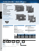
Mobile MF Series
AIR COOLED MF
Features
n
Same as M Series with DC Fan or
Hydraulic Motor
n
3/8” Tube Size
n
Aluminum Fins
n
Low AMP Draw 12 or 24 Volt DC Motor
n
Heavy Duty Construction
n
Optional Serviceable Relief
Bypass Valve
n
Optional Fan Control Switch
n
Long Life Hydraulic Motors
n
Heat Removal TO 50,000 BTU/Hr.
n
Oil Flows to 150 GPM
n
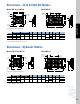
Mounting Brackets Included
n
SAE, NPT or 37° Flare Oil Connections
n
Rugged Steel Manifolds
Materials
Tubes Copper
Fins Aluminum
Turbulators Steel
Manifolds S t e e l
Fan Assembly High Impact Plastic
Motor Displacement . 2 2 i n
3
/Rev. (Hydraulic)
Maximum Pressure 2000 PSI (Hydraulic)
Allowable Backpressure 1000 PSI (Hydraulic)
Relief Bypass Valve Option
MODEL DESCRIPTION
MFR-15 3/4”, external, all steel valve.
Available in either 30 PSI or 60 PSI
settings. May be removed for
servicing.
MFR-30 1-1/2”, external, all steel valve.
MFR-60 Available in either 30 PSI or 60 PSI
settings. May be removed for
servicing.
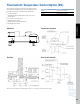
Ratings
Operating Pressure 300 psi
Operating Temperature 350° F
DC current required Hydraulic Motor Data
Number
Oil Flow Required Minimum Operating Maximum Fan Speed
of Fans 12 Volt 24 Volt (GPM) Pressure (PSI) (RPM)
1 12.5 amps 6.3 amps 2.1 300 2200
2 25 amps 12.6 amps 4.2 300 2200
Motor
Specification
NM - No Motor
4A - 12 Volt DC
4B - 24 Volt DC
9 - Hydraulic Motor
–
*Other connection types available. Please consult factory for assistance.
How to Order
Model
Series
MF
MFR - Relief
Bypass
Included
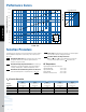
Model Size Selected
– –
Connection
Type*
1 - NPT
2 - SAE
3 - BSPP
7 - 37° Male Flare
Relief Bypass
Blank - No Bypass
30 - 30 psi
60 - 60 psi
–
ADD FOR MFR MODELS ONLY