
User guide

EPM00059EN 0407
How to contact Alfa Laval
Contact details for all countries
are continually updated on our website.
Please visit www.alfalaval.com to
access the information directly.
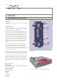
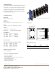
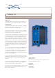
Working principle
Channels are formed between the plates and the corner ports
are arranged so that the two media ow through alternate
channels. The heat is transferred through the plate between
the channels, and complete counter-current ow is created
for highest possible efciency. The corrugation of the plates
provides the passage between the plates, supports each
plate against the adjacent one and enhances the turbulence,
resulting in efcient heat transfer.
Standard materials
Frame plate
Mild steel, Epoxy painted
Nozzles
Carbon steel
Metal lined; Stainless steel, Alloy 20/18/6 or Titanium
Plates
Stainless steel AISI 316, Alloy 20/18/6 or Titanium
Gaskets
Field gaskets Nitrile, EPDM
Ring gaskets Chloroprene, EPDM and Nitrile
Connections
FG PED Size 150 mm DIN PN16
FG ASME Size 6" ANSI 150
FD PED Size 150 mm DIN PN25
FD ASME Size 6" ANSI 300
Technical data
Mechanical design pressure (g) / temperature
FG PED 1.6 MPa / -50 to 180°C
FG ASME 150 psig / -40 to 350°F
FD PED 2.5 MPa / -50 to 180°C
FD ASME 300 psig / -40 to 350°F
Maximum heat transfer surface
165 m² (1780 sq. ft)
Particulars required for quotation
– Flow rates or heat load
– Temperature program
– Physical properties of liquids in question (if not water)
– Desired working pressure
– Maximum permitted pressure drop
– Available steam pressure
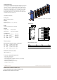
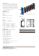
Flow principle of a plate heat exchanger
All rights reserved for changes in specications
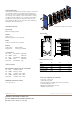
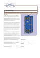
Dimensions
Measurements (mm)
Type H W h
MK15-FG 1486 650 221
MK15-FD 1486 650 221
The number of tightening bolts may vary depending on pressure rating.
THERMAL TRANSFER SYSTEMS, INC.
SALES@THERMALTRANSFERSYSTEMS.COM
PH: 800-527-0131 FAX: 972-242-7568