
Owner's manual

EKT
www.thermaltransfer.com TTPSales@thermasys.com 262.554.8330
91
WATER COOLED EKT
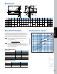
Performance Curves
Dimensions
9.75
MODEL
A B
NPT or
BSPF
C D E F G H
J
Q R
EKT-508
EKT-518
EKT-708
EKT-718
EKT-1012
EKT-1024
8.87
18.87
8.72
18.72
12.55
24.55
6.79
Approx.
Ship Wt.
Net. Wt.
SAE
J
NPT or
BSPF
K
T1 T2 W
10.38
3.52
2.55
5.05
1.84
2.22
1.67
1.68
2.23
1.62
1.12
2.38
3.94
2.44
4.69
1.25
.50
1.19
1-1/2"
3/4"
#24
#12
3/4"
3/8"
1"
12
6
8.94
5.60
9.62
4.00
2.25
4.38
—
.79
1.12
.70
.62
11
14
23
30
42
58
14
16
27
34
46
63
Oil “Outlet”
“C” Dia.
A
D
Oil
“Inlet”
.34" Dia. Holes
“Q” Quantity
“R” Dia. Bolt Circle
T1 and T2 Radii
represent oil tank
cut out.
H
G
T1 Rad.
T2 Rad.
E
W
K (2 Places)
B
J
F
NOTE: We reserve the right to make reasonable design changes without notice. Certified drawings are available upon request. All dimensions in inches. Tank gasket is included.
BSPP threads are 55° full form whitworth.
[ ]
Average Oil SSU A B
50 0.84 0.6
100 1.0 1.0
200 1.14 2.0
300 1.24 3.1
400 1.31 4.1
500 1.37 5.1
Viscosity Corrections
EKT-718
EKT-1024
EKT-1012
EKT-518
EKT-708
EKT-508
2
2.5
4
5
6
8 9
10
15
20 25 30 40 50 60
7
8
9
10
15
20
25
30
40
50
60
70
80
90
100
150
5
3
7
4
3
6
OIL FLOW - GAL/MIN
HP HEAT REMOVED IN COOLER
Oil “Outlet”
“C” Dia.
A
D
Oil
“Inlet”
.34" Dia. Holes
“Q” Quantity
“R” Dia. Bolt Circle
T1 and T2 Radii
represent oil tank
cut out.
H
G
T1 Rad.
T2 Rad.
E
W
K (2 Places)
B
J
F
Unit Size Shell Side GPM) Tube Side(GPM)
500 20 6
700 60 12
1000 80 28
If maximum allowable flow rates are exceeded, premature failure may occur.
Maximum Flow Rates
Selection Procedure
Performance Curves are based on a 40°F approach temperature, a 2:1 oil
to water ratio and an average oil viscosity of 100 SSU. Example: oil leaving
cooler at 125°F with 85°F cooling water (125°F - 85°F = 40°F). The 2:1 oil
to water ratio means that for every GPM of oil circulated, a minimum of
1/2 GPM of water must must be circulated to obtain the curve results.
Step 1 Corrections for approach temperature and oil viscosity.
HP
Heat Removed in Cooler =
HP
Actual x
40°F
x Correction A
Oil out and °F - Water in °F
Step 2 Oil Pressure Drop Coding: l = 5 PSI; n = 10 PSI. Curves
having no pressure drop symbol indicate that the oil pressure drop is less
than 5 PSI to the highest oil flow rate for that curve. Multiply curve oil
pressure drop by Correction B.