
Manual

CA -2000
TTPSales@thermasys.com 262.554.8330 www.thermaltransfer.com
98
FLUID COOLING
|
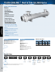
Shell & Tube CA-2000 Series
WATER COOLED
CA-2000
COPPER & STEEL CONSTRUCTION
Features
n
Super High Flow
n
Largest Flow Rates &
Heat Transfer Available
n
ASME Code
n
Rugged Steel Construction
n
Custom Designs Available
n
Competitively Priced
n
3/8” & 5/8” Tubes Available
n
Max. 10” Diameter, 12’ Long
n
150# ANSI/ASME Flanged Shell
Connections (Metric Available)
n
Optional Construction on CA-2000
Series: Tubes, Tubesheets, and End
Bonnets
n
End Bonnets Removable For Servicing
n
Saddle Brackets For Incremental
Mounting
n
ASME Code (Section VIII, Division I)
and TEMA-C Construction
Available (Consult Factory for Ordering
Information)
Materials
Headers Steel
Shell Steel
Shell Connections Steel
B a f f l e s B r a s s
End Bonnets Cast Iron
Mounting Brackets Steel/Cast Iron
Gaskets Nitrile Rubber/Cellulose Fiber
Nameplate Aluminum Foil
Ratings
Maximum Shell Pressure 150 psi
Maximum Tube Side Pressure 150 psi
Maximum Temperature 300° F
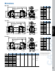
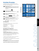
How to Order
Model Size Selected
Tube
Diameter
Code
6 - 3/8”
10 - 5/8”
Tubeside
Passes
0 - One Pass
T - Two Pass
F - Four Pass
–
Baff le
Spacing
Cooling
Tube
Material
Blank - Copper
CN - CuNi
SS - Stainless
Steel
AD - Admiralty
Brass
End
Bonnet
Material
Blank - Cast Iron
NP - Electroless
Nickel Plate
Tubesheet
Material
Blank - Cast Iron
W - CuNi
S - Stainless
Steel
Zinc
Anodes
Blank - None
Z - Zinc
– –
–
––
–
–
Model
Series
CA
CAM
Maximum Flow Rates
Shell Side (GPM) Tube Side GPM
6” 9” One Two Four
Baff le Baff le Pass Pass Pass
210 320 652 326 163
CA = NPT tubeside bottom connections; ASME/ANSI flange shell top connections.
CAM = BSPP shellside connections; BSPP tubeside connections.