
Installation guide


®
INSTALLATmON iNSTRUCTIONS
MODEL WD24/WD27/WD30
WARMING DRAWER
PLEASE READ ENTtRE iNSTRUCTiONS BEFORE PROCEEDnNG.
iNSTALLATiON MUST COMPLY WITH ALL LOCAL CODES.
The warming drawer is completely self-contained and ready for installation.
Power Supply: 120Volts, 15 Ampere, 60 Hz.
iMPORTANT: Before turning on power, be sure that the control is turned to "OFF."
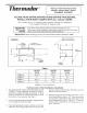
FIGURE 1
Frame 1ol/2" Min. to
Cabinet
Allow 3ol/2" in front for
drawer handle clearance
Wal_
Receptacle
Support
Brackets
.
,
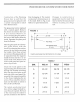
Table 1
MODEL MODEL MODEL
WD24 WD27 WD30
DIM A 22-3/4" 25-3/4" 25-3/4"
DIM B 9" 10" 10"
DIM C 20-1/4 '' 22°1/4"
DIM D 3/8" 9/lg' 2-!/8"
TABLE 1: Cut out Dimensions
INSTALLING THE WARMING DRAWER
The opening ha the wall or cabinet should be A wide
x B high x C deep minimum as shown in Table 1.
Install two support brackets (provided) 8" from
the front of the wall or cabinet at the same level as
the bottom of the opening. (See Fig. 1)
Push unit into opening until it clears support brack-
ets and supports its own weight.
Push unit tight against wall or cabinet and secure
with four screws (provided). Two screws go into
top two corners of front frame, the others go at the
bottom of the front frame.
.
When sta: king one drawer above the other or side-
by-side installation, allow 1-1/2" between cutouts.
If you desire a gap between the units, allow more
space between the cutouts. Allow 2-1/2" between
cutouts when installing the warming drawer un-
der a wall oven.