
Installation Manual
English 12
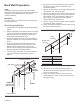
Wire Connection
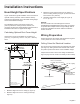
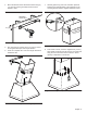
Wire Routing
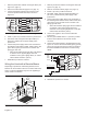
1. Run a 120V AC, 15 amp circuit power cable from the
service panel through one of the holes in the top plate.
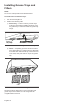
2. Connect black wire to power supply black wire, white
wire to power supply white wire and green wire to
green wire or bare wire.
3. Place all wiring connections inside the junction box
channel. Reinstall on the top plate. Ensure that the
wires are secure and that no wires are pinched.
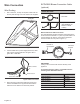
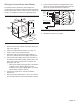
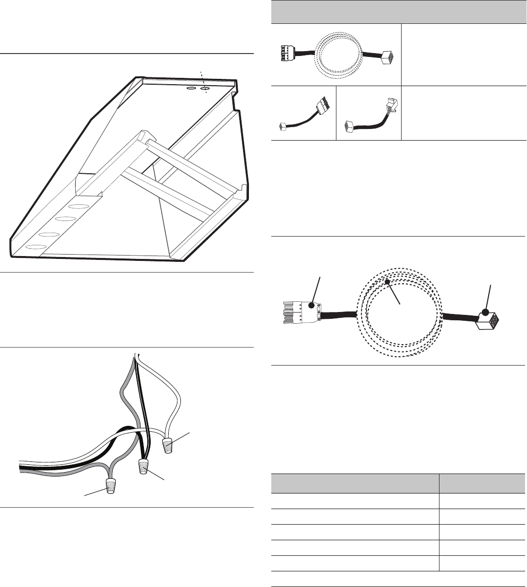
EXTNCB25 Blower Connection Cable
(optional)
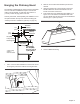
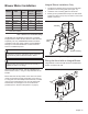
Blower Extension Cable Connection
The internal blower harness should be routed through the
knockout and secured with a 1” (25.4 mm) strain relief. The
remote harness can then be connected to the blower
harness outside the unit (refer to Figure 11).
IMPORTANT:
Cutting of the connector will void the warranty of the
appliance.
The blower extension cable is compatible with the
following Inline & Remote blowers:
Figure 11: Route Wire
Figure 12: Wire Connection
Route Wire
White to white
Black to black
Green to green
or bare wire
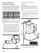
PARTS INCLUDED:
1 – 25ft cable
2 – Adapter Cables
(NOT NEEDED for
HPCN or HPCB
models)
Figure 13: Optional Blower Connection Cable
BLOWER SKU
Remote Blower VTR630*
Remote Blower VTR1030*
Remote Blower VTR1330*
Inline Blower VTI610*
Inline Blower VTI1010*
*Indicates a letter designating the release year.
25ft cable
Connects
to Hood
Connects to
Remote or
Inline blower